MCP2150DM Microchip Technology, MCP2150DM Datasheet - Page 32
MCP2150DM
Manufacturer Part Number
MCP2150DM
Description
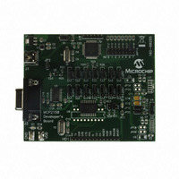
BOARD DEMO FOR MCP2150
Manufacturer
Microchip Technology
Specifications of MCP2150DM
Main Purpose
Interface, IrDA
Embedded
Yes, MCU, 8-Bit
Utilized Ic / Part
MCP2150
Primary Attributes
IrDA Controller with PIC18F MCU
Secondary Attributes
USB Interface
Processor To Be Evaluated
MCP2150, MCP2155
Processor Series
MCP215x
Interface Type
USB
Lead Free Status / RoHS Status
Lead free / RoHS Compliant
Lead Free Status / RoHS Status
Lead free / RoHS Compliant, Lead free / RoHS Compliant


MCP2150 Developer’s Board User’s Guide
FIGURE 2-9:
DS51869A-page 32
Note 1:
Monitor
2:
3:
(to IrDA Dongle)
HyperTerminal
Program Window A
The PC may be a Notebook with an Integrated IR port. This operates as the Primary
Device.
Serial cable. Connects Secondary Device to PC.
USB cable (for power only).
HyperTerminal
Program Window B
(Com 1)
2.3.4
In Demo #4, the MCP2150 Developer’s Board will communicate to the PC (or IrDA to
serial interface Dongle) data received on the DB-9 port.
This demo shows the MCP2150 converting data between the IR port and the Host
UART port. The Primary Device’s IR packet is decoded and any data is extracted and
transmitted on the Host UART interface. Data received on the Host UART interface is
formatted into the IR data packet and transmitted to the Primary device.
Figure 2-9 shows the system setup for this test, while Figure 2-10 shows the jumper
configuration for the MCP2150 board. Lastly, Table 2-5 shows the steps for Demo #4
operation.
DEMO #4 SYSTEM BLOCK DIAGRAM
Hyperterminal to Serial Port Settings
The com port settings should be configured as:
• 115,200 Baud
• 8-bits
• No Parity
• One Stop
• Hardware Flow Control
¬
(1)
(2)
Demo #4 Operation - IR / UART (DB-9) Pass Through PIC Mode
PC
System #1
Serial (UART or USB)
to IrDA Dongle
(1)
(1)
System #2
MCP2150 Developer’s
Board
© 2009 Microchip Technology Inc.
Com 1
(2)
(3)
Related parts for MCP2150DM
Image
Part Number
Description
Manufacturer
Datasheet
Request
R

Part Number:
Description:
Manufacturer:
Microchip Technology Inc.
Datasheet:
Part Number:
Description:
Manufacturer:
Microchip Technology Inc.
Datasheet:
Part Number:
Description:
Manufacturer:
Microchip Technology Inc.
Datasheet:
Part Number:
Description:
Manufacturer:
Microchip Technology Inc.
Datasheet:
Part Number:
Description:
Manufacturer:
Microchip Technology Inc.
Datasheet:
Part Number:
Description:
Manufacturer:
Microchip Technology Inc.
Datasheet:
Part Number:
Description:
Manufacturer:
Microchip Technology Inc.
Datasheet:
Part Number:
Description:
Manufacturer:
Microchip Technology Inc.
Datasheet: