MCP212XEV-DB Microchip Technology, MCP212XEV-DB Datasheet - Page 23
MCP212XEV-DB
Manufacturer Part Number
MCP212XEV-DB
Description
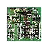
BOARD DEMO FOR MCP212X
Manufacturer
Microchip Technology
Specifications of MCP212XEV-DB
Main Purpose
Interface, Infrared Transceiver
Utilized Ic / Part
MCP2120, MCP2122
Processor To Be Evaluated
MCP2122 and MCP2120
Interface Type
UART
Silicon Manufacturer
Microchip
Silicon Core Number
MCP2120, MCP2122
Kit Contents
MCP2122 Daughter Board, Docs
Features
8-Pin And 14-Pin Sockets, Three Optical Transceiver Circuits
Mcu Supported Families
MCP212x
Rohs Compliant
Yes
Lead Free Status / RoHS Status
Contains lead / RoHS non-compliant
Secondary Attributes
-
Embedded
-
Primary Attributes
-
Lead Free Status / Rohs Status
Lead free / RoHS Compliant
Available stocks
Company
Part Number
Manufacturer
Quantity
Price
Company:

Part Number:
MCP212XEV-DB
Manufacturer:
MICROCHIP
Quantity:
12 000


© 2005 Microchip Technology Inc.
2.5.2.2
The MCP2120 (U1) implements an IrDA standard encoder/decoder. The baud rate is
determined by the device frequency and the state of the BAUD2:BAUD0 pins. The
MCP2120 also has a Software Baud Rate mode which controls the baud rate via the
Host Controller software.
The key signals for the MCP2120-to-microcontroller (Host UART) interface are shown
in Table 2-6. The key signals for the MCP2120-to-IR transceiver circuit are shown in
Table 2-7.
TABLE 2-6:
TABLE 2-7:
In addition to the signals described in Table 2-6 and Table 2-7, the MCP2120 RESET
input is connected to the RESET output of the Host Controller. The EN input can be
either hard-wired or controlled by the Host Controller.
TXIR
RXIR
Legend: A = Analog
TX
RX
BAUD0
BAUD1
BAUD3
MODE
Legend: TTL = TTL compatible input
Pin Name
Name
Pin
I = Input
I = Input
MCP2120 OPERATION
Number
Number
(PDIP)
(PDIP)
Pin
Pin
MCP2120 HOST UART INTERFACE PINS
MCP2120 IR INTERFACE PINS
12
10
11
6
5
9
8
7
Type
Type
Pin
Pin
O
O
I
I
I
I
I
I
Buffer
Buffer
Type
Type
ST
TTL
TTL
TTL
TTL
TTL
—
—
Installation and Operation
Asynchronous transmit to IrDA
transceiver
Asynchronous receive from an infrared transceiver
P = Power
O = Output
ST = Schmitt Trigger input with CMOS levels
O = Output
BAUD2:BAUD0 specifies the Baud rate of the
Asynchronous receive; from Host Controller UART
Asynchronous transmit; to Host Controller UART
device, or if the device operates in Software Baud
Rate mode
Selects the device mode (Data/Command) for
Software Baud Rate operation
Description
Description
®
standard
DS51571A-page 19
Related parts for MCP212XEV-DB
Image
Part Number
Description
Manufacturer
Datasheet
Request
R

Part Number:
Description:
Manufacturer:
Microchip Technology Inc.
Datasheet:
Part Number:
Description:
Manufacturer:
Microchip Technology Inc.
Datasheet:
Part Number:
Description:
Manufacturer:
Microchip Technology Inc.
Datasheet:
Part Number:
Description:
Manufacturer:
Microchip Technology Inc.
Datasheet:
Part Number:
Description:
Manufacturer:
Microchip Technology Inc.
Datasheet:
Part Number:
Description:
Manufacturer:
Microchip Technology Inc.
Datasheet:
Part Number:
Description:
Manufacturer:
Microchip Technology Inc.
Datasheet:
Part Number:
Description:
Manufacturer:
Microchip Technology Inc.
Datasheet: