MCP73871EV Microchip Technology, MCP73871EV Datasheet - Page 12
MCP73871EV
Manufacturer Part Number
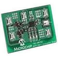
MCP73871EV
Description
EVALUATION BOARD FOR MCP73871
Manufacturer
Microchip Technology
Type
Battery Managementr
Specifications of MCP73871EV
Main Purpose
Power Management, Battery Charger
Embedded
No
Utilized Ic / Part
MCP73871
Primary Attributes
1 Cell- Li-Ion / Li-Pol, 4.2V @ 100 or 500mA: USB, 1.65A: AC Adaptor
Secondary Attributes
LED Status Indicators
Silicon Manufacturer
Microchip
Application Sub Type
Battery Charger
Kit Application Type
Power Management - Battery
Silicon Core Number
MCP73871
Product
Power Management Modules
Kit Contents
Board
Lead Free Status / RoHS Status
Lead free / RoHS Compliant
For Use With/related Products
MCP73871
Lead Free Status / RoHS Status
Lead free / RoHS Compliant


2.3
DS51755A-page 8
GETTING STARTED
The MCP73871 Evaluation Board is fully assembled and tested for charging a
single-cell Li-Ion or Li-Polymer battery with or without system load.
2.3.1
2.3.1.1
1. Connect the positive battery terminal to V
2. Connect the 5V - 6V DC power supply Negative Terminal to V
3. Connect the 5V - 6V DC power supply Positive Terminal to V
4. Connected positive of load to OUT (TP3) on the board and negative of load to
5. The maximum current that system load requires should not violate the specifica-
6. It should initiate the battery charging cycle when drive CE (TP6) high. Drive CE
7. Position the DIP Switch #2 (SW2) to “AC” allows maximum input current of 1.8A
8. Position the DIP Switch #2 (SW2) to “USB” limits the input current to meet USB
9. When DIP Switch #2 (SW2) is positioned at USB; position the DIP Switch #1
10. Remove DC power supply, the load should be supported by the Li-Ion battery
Note:
terminal to V
either V
tion of Li-Ion battery manufacturer (Typical at 1C or less) or 1A for safety and
performance concerns.
(TP6) low disables the Li-Ion battery charger function.
to support both system load and Li-Ion battery charger at 1000 mA fast charge
current rate.
specifications.
(SW1) to “High” limits total input current to 500 mA and “Low” for maximum input
current at 100 mA.
now.
Power Input and Output Connection
POWERING THE MCP73871 EVALUATION BOARD
Fast Charge Current and Termination Current can be easily programmed
with various resistors that based on the Figure 2-1.
The Li-Ion battery pack can be replaced with test circuit or electronic load
that can sink current with DC power supply. Please refer to Figure 2-2.
SS
(TP1 or TP5). The system load can be a power resistor or E-Load.
SS
(TP1 or TP5).
BAT+
(TP4) and negative battery
© 2008 Microchip Technology Inc.
DD
SS
(TP2).
(TP1 or TP5).
Related parts for MCP73871EV
Image
Part Number
Description
Manufacturer
Datasheet
Request
R

Part Number:
Description:
Manufacturer:
Microchip Technology Inc.
Datasheet:
Part Number:
Description:
Manufacturer:
Microchip Technology Inc.
Datasheet:
Part Number:
Description:
Manufacturer:
Microchip Technology Inc.
Datasheet:
Part Number:
Description:
Manufacturer:
Microchip Technology Inc.
Datasheet:
Part Number:
Description:
Manufacturer:
Microchip Technology Inc.
Datasheet:
Part Number:
Description:
Manufacturer:
Microchip Technology Inc.
Datasheet:
Part Number:
Description:
Manufacturer:
Microchip Technology Inc.
Datasheet:
Part Number:
Description:
Manufacturer:
Microchip Technology Inc.
Datasheet: