NCP5104BA36WGEVB ON Semiconductor, NCP5104BA36WGEVB Datasheet - Page 2
NCP5104BA36WGEVB
Manufacturer Part Number
NCP5104BA36WGEVB
Description
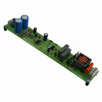
EVAL BOARD FOR NCP5104BA36WG
Manufacturer
ON Semiconductor
Datasheets
1.NCP5104DR2G.pdf
(15 pages)
2.NCP5104BA36WGEVB.pdf
(3 pages)
3.NCP5104BA36WGEVB.pdf
(6 pages)
Specifications of NCP5104BA36WGEVB
Design Resources
NCP5104 Demo Board BOM NCP5104BAL36WEVB Gerber Files NCP5104 Demo Board Schematic
Main Purpose
Lighting, Ballast Control
Embedded
No
Utilized Ic / Part
NCP5104
Primary Attributes
Output Power 36W, PL-L Type
Secondary Attributes
Input Range 85 ~ 145 Vac or 184 ~ 265 Vac
Silicon Manufacturer
On Semiconductor
Silicon Core Number
NCP5104
Kit Application Type
Lighting
Application Sub Type
Ballast
Development Tool Type
Hardware - Eval/Demo Board
Rohs Compliant
Yes
Leaded Process Compatible
Yes
Lead Free Status / RoHS Status
Lead free / RoHS Compliant
For Use With/related Products
NCP5104BA36WG
Other names
NCP5104BA36WGEVBOS


Test Procedure:
1. First of all check if you need or not the jumper #2 (J2 on the board close the diode bridge). This jumper
2. Connect the test setup as shown above:
3. Apply 230 Vac if European mains or 110 Vac for the US mains on the input connector.
4. Compare Iload and Vload with the following table according your input mains voltage.
5. If you get the correct output and input voltage, you can now connect a 36 W fluorescent tube on the
Test results:
Input mains
must be removed in case of European mains (230 Vac input voltage) and have to placed in case of US
mains (110 Vac). This jumper is used to build a voltage doublers just after the bridge diode in case of US
mains input voltage range.
• AC source
• Voltmeter and Ampere meter on the load
• Load on the output
output (see the ballast connection figure).
European
US
input voltage:
Yes
132 Vrms
Removed
J2
max
Vin (Vrms)
230 V
110 V
Iin (Arms)
278 mA
514 mA
Vload (Vrms)
303 V
263 V
Iload (Arms)
340 mA
370 mA
Related parts for NCP5104BA36WGEVB
Image
Part Number
Description
Manufacturer
Datasheet
Request
R

Part Number:
Description:
Half Bridge Driver
Manufacturer:
ON Semiconductor
Datasheet:
Part Number:
Description:
ON Semiconductor [VOLTAGE REGULATOR]
Manufacturer:
ON Semiconductor
Datasheet:
Part Number:
Description:
357-036-542-201 CARDEDGE 36POS DL .156 BLK LOPRO
Manufacturer:
ON Semiconductor
Datasheet:
Part Number:
Description:
357-036-542-201 CARDEDGE 36POS DL .156 BLK LOPRO
Manufacturer:
ON Semiconductor
Datasheet:
Part Number:
Description:
357-036-542-201 CARDEDGE 36POS DL .156 BLK LOPRO
Manufacturer:
ON Semiconductor
Datasheet:
Part Number:
Description:
357-036-542-201 CARDEDGE 36POS DL .156 BLK LOPRO
Manufacturer:
ON Semiconductor
Datasheet:
Part Number:
Description:
357-036-542-201 CARDEDGE 36POS DL .156 BLK LOPRO
Manufacturer:
ON Semiconductor
Datasheet:
Part Number:
Description:
357-036-542-201 CARDEDGE 36POS DL .156 BLK LOPRO
Manufacturer:
ON Semiconductor
Datasheet:
Part Number:
Description:
357-036-542-201 CARDEDGE 36POS DL .156 BLK LOPRO
Manufacturer:
ON Semiconductor
Datasheet:
Part Number:
Description:
357-036-542-201 CARDEDGE 36POS DL .156 BLK LOPRO
Manufacturer:
ON Semiconductor
Datasheet:
Part Number:
Description:
357-036-542-201 CARDEDGE 36POS DL .156 BLK LOPRO
Manufacturer:
ON Semiconductor
Datasheet:
Part Number:
Description:
357-036-542-201 CARDEDGE 36POS DL .156 BLK LOPRO
Manufacturer:
ON Semiconductor
Datasheet:
Part Number:
Description:
Manufacturer:
ON Semiconductor
Datasheet:
Part Number:
Description:
Manufacturer:
ON Semiconductor
Datasheet: