EVB-USB2514Q36-BAS SMSC, EVB-USB2514Q36-BAS Datasheet - Page 3
EVB-USB2514Q36-BAS
Manufacturer Part Number
EVB-USB2514Q36-BAS
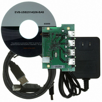
Description
BOARD EVAL FOR USB2514/USB2514I
Manufacturer
SMSC
Specifications of EVB-USB2514Q36-BAS
Main Purpose
Interface, USB 2.0 Hub
Embedded
No
Utilized Ic / Part
USB2514, USB2514I
Primary Attributes
Quad Port Hub, High Speed (480Mbps), I2C/SMBus
Secondary Attributes
Overcurrent Protection, Port Power Switching, ESD Protection
Interface Type
USB
Operating Supply Voltage
5 V
Product
Interface Modules
Lead Free Status / RoHS Status
Lead free / RoHS Compliant
For Use With/related Products
USB2514
Other names
638-1043
EVB-USB2514Q36-BAS (USB2514/USB2514I)
EVB-USB2514Q36-BAS (USB2514/USB2514I)
Available stocks
Company
Part Number
Manufacturer
Quantity
Price
Company:

Part Number:
EVB-USB2514Q36-BAS
Manufacturer:
Standard
Quantity:
1


EVB-USB2514Q36-BAS, USB2513 and USB2512 36-Pin QFN Evaluation Board, Revision C User Manual
SMSC EVB-USB2514Q36-BAS Revision C
2 Hardware Configuration
2.1
2.1.1
2.1.2
2.1.3
2.1.4
2.1.5
Hardware Description
The EVB-USB2514Q36-BAS has one onboard regulator, which generates +3.3 VDC from a +5.0 VDC
power supply. An alternate footprint U5 was added to support industrial temperature range. The
alternate footprint supports a larger package and has ties into the ground plane for better thermal
dissipation. The USB2514 generates is own on chip +1.8 VDC supply. The USB2514 Hub consumes
power from the +3.3 VDC supply while the MIC2026 Power distribution switch consumes power from
the +5.0 VDC supply. The MIC2026 Power distribution switch supplies downstream power to each
attached device.
Port Assignment
Downstream ports are numbered 1 through 4 with individual port power controllers. The port power
controllers provide 5 Volt power with over-current protection to the downstream devices. Upstream and
downstream port connectors have USB 2.0 compliant decoupling, filtering for EMI on signal ground
and power, and a separate shield ground. ESD protection for USB signals is provided by diode bridges
and common mode chokes. This gives protection up to 25 kV direct contact to USB signals.
Optional pull-up resistors can be placed to disable a USB port, see the schematic on the CD-ROM
included with your EVB-USB2514Q36-BAS for implementation.
HUB Configuration
The EVB-USB2514Q36-BAS has been configured to support internal default configuration with
strapping options enabled as determined by the state of CFG_SEL[1] and CFG_SEL[0] pins
immediately after reset. The internal +1.8 VDC regulator supplies voltage to the oscillator and PLL is
turned off during suspend to minimize suspend current.
Powered State LED
An optional LED (LED5) indicates when +5.0 VDC power is present.
Active State LED
An optional LED (LED6) indicates when the hub is active (configured and not suspended).
Port Power LEDs
LED1, LED2, LED3, and LED4 indicate when port power is available to the associated downstream
USB port.
USER MANUAL
3
Revision 0.3 (08-12-10)
Related parts for EVB-USB2514Q36-BAS
Image
Part Number
Description
Manufacturer
Datasheet
Request
R

Part Number:
Description:
BOARD EVAL FOR USB2514 48-QFN
Manufacturer:
SMSC
Datasheet:
Part Number:
Description:
Networking Modules & Development Tools USB2514 Evaluation Board
Manufacturer:
SMSC
Datasheet:

Part Number:
Description:
FAST ETHERNET PHYSICAL LAYER DEVICE
Manufacturer:
SMSC Corporation
Datasheet:
Part Number:
Description:
357-036-542-201 CARDEDGE 36POS DL .156 BLK LOPRO
Manufacturer:
SMSC Corporation
Datasheet:
Part Number:
Description:
357-036-542-201 CARDEDGE 36POS DL .156 BLK LOPRO
Manufacturer:
SMSC Corporation
Datasheet:
Part Number:
Description:
357-036-542-201 CARDEDGE 36POS DL .156 BLK LOPRO
Manufacturer:
SMSC Corporation
Datasheet:
Part Number:
Description:
4-PORT USB2.0 HUB CONTROLLER
Manufacturer:
SMSC Corporation
Datasheet:
Part Number:
Description:
Manufacturer:
SMSC Corporation
Datasheet:
Part Number:
Description:
Manufacturer:
SMSC Corporation
Datasheet:
Part Number:
Description:
FDC37C672ENHANCED SUPER I/O CONTROLLER WITH FAST IR
Manufacturer:
SMSC Corporation
Datasheet:
Part Number:
Description:
COM90C66LJPARCNET Controller/Transceiver with AT Interface and On-Chip RAM
Manufacturer:
SMSC Corporation
Datasheet:
Part Number:
Description:
Manufacturer:
SMSC Corporation
Datasheet:
Part Number:
Description:
Manufacturer:
SMSC Corporation
Datasheet:
Part Number:
Description:
Manufacturer:
SMSC Corporation
Datasheet: