DC-VIDEO-TVP5146N Altera, DC-VIDEO-TVP5146N Datasheet - Page 11
DC-VIDEO-TVP5146N
Manufacturer Part Number
DC-VIDEO-TVP5146N
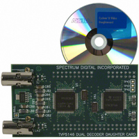
Description
VIDEO DAUGHTER CARD
Manufacturer
Altera
Series
Stratix® IIIr
Datasheets
1.EP3SL150F780C4N.pdf
(16 pages)
2.EP3SL150F780C4N.pdf
(332 pages)
3.DC-VIDEO-TVP5146N.pdf
(58 pages)
Specifications of DC-VIDEO-TVP5146N
Main Purpose
Video, Daughter Card
Embedded
No
Utilized Ic / Part
Altera Dev Kits
Primary Attributes
Dual Composite Video Input - NTSC or PAL
Secondary Attributes
10-bit BT.656 Output, Compatible with Expansion Connector, Standard on Most Altera Development Kits
Lead Free Status / RoHS Status
Lead free / RoHS Compliant
Other names
544-1704


Altera Corporation
Note to
(1)
VGA D/A Converter
Audio CODEC
CompactFlash card
connector
Debugging Interfaces
Mictor connectors
Expansion Interfaces
Analog Devices
connector
TI-EVM connectors
Expansion Prototype
Connectors
Table 2–1. Stratix II EP2S180 DSP Development Board Components & Interfaces (Part 2 of 2)
Component/
These headers can be used to interface to Analog Devices A/D converter evaluation boards. They are designated
as J5 and J6, and interface to Analog Devices AD6645/9433/9430 external A/D converters.
Interface
Table
(1)
2–1:
f
I/O
I/O
I/O
I/O
Expansion
Expansion
Expansion
Type
Environmental Requirements
The Stratix II EP2S180 DSP development board must be stored between
–40° C and 100° C. The recommended operating temperature is between
0° C and 55° C.
w
The DSP Development Kit, Stratix II Professional Edition includes a heat
sink and fan combination, also known as an active heat sink. Depending
on the specific requirements of your application, this level of cooling
may not be necessary.
U45
U5
CON1
J20
J5, J6
J31, J33
J23 - J25,
J26 - J28
Designation
The Stratix II EP2S180 DSP development board can be damaged
without proper anti-static handling.
Board
Stratix II EP2S180 DSP Development Board Reference Manual
One 8-bit, 180 megapixels-per-second triple D/A
converter for VGA output
96-KHz stereo audio CODEC
CompactFlash card connector
One Mictor header connected to 33 pins on the Stratix II
device (32 data signals, 1 clock signal) for use with an
external logic analyzer.
Interface to Analog Device’s A/D converters via two
40-pin connectors.
Interface to the TI-EVM. (The connectors are on the
reverse side of the board.)
The board provides two custom interfaces to daughter
cards via 74-pin headers. (These pins can also be used
for general I/O.)
These connectors are referred to on the board as
“Santa Cruz Daughter Card 1“ and “Santa Cruz
Daughter Card 2”
Core Version a.b.c variable
Board Components & Interfaces
Description
2–3
Related parts for DC-VIDEO-TVP5146N
Image
Part Number
Description
Manufacturer
Datasheet
Request
R

Part Number:
Description:
CYCLONE II STARTER KIT EP2C20N
Manufacturer:
Altera
Datasheet:


Part Number:
Description:
CPLD, EP610 Family, ECMOS Process, 300 Gates, 16 Macro Cells, 16 Reg., 16 User I/Os, 5V Supply, 35 Speed Grade, 24DIP
Manufacturer:
Altera Corporation
Datasheet:
Part Number:
Description:
CPLD, EP610 Family, ECMOS Process, 300 Gates, 16 Macro Cells, 16 Reg., 16 User I/Os, 5V Supply, 15 Speed Grade, 24DIP
Manufacturer:
Altera Corporation
Datasheet:
Part Number:
Description:
Manufacturer:
Altera Corporation
Datasheet:
Part Number:
Description:
CPLD, EP610 Family, ECMOS Process, 300 Gates, 16 Macro Cells, 16 Reg., 16 User I/Os, 5V Supply, 30 Speed Grade, 24DIP
Manufacturer:
Altera Corporation
Datasheet:
Part Number:
Description:
High-performance, low-power erasable programmable logic devices with 8 macrocells, 10ns
Manufacturer:
Altera Corporation
Datasheet:
Part Number:
Description:
High-performance, low-power erasable programmable logic devices with 8 macrocells, 7ns
Manufacturer:
Altera Corporation
Datasheet:
Part Number:
Description:
Classic EPLD
Manufacturer:
Altera Corporation
Datasheet:
Part Number:
Description:
High-performance, low-power erasable programmable logic devices with 8 macrocells, 10ns
Manufacturer:
Altera Corporation
Datasheet:
Part Number:
Description:
Manufacturer:
Altera Corporation
Datasheet:
Part Number:
Description:
Manufacturer:
Altera Corporation
Datasheet:
Part Number:
Description:
Manufacturer:
Altera Corporation
Datasheet:
Part Number:
Description:
CPLD, EP610 Family, ECMOS Process, 300 Gates, 16 Macro Cells, 16 Reg., 16 User I/Os, 5V Supply, 25 Speed Grade, 24DIP
Manufacturer:
Altera Corporation
Datasheet: