STK-AOB3202405 Amulet Technologies LLC, STK-AOB3202405 Datasheet - Page 7
STK-AOB3202405
Manufacturer Part Number
STK-AOB3202405
Description
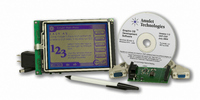
KIT STARTER 5.7" ONBOARD MODULE
Manufacturer
Amulet Technologies LLC
Series
Amulet OnBoard (AOB)r
Specifications of STK-AOB3202405
Main Purpose
Displays, Graphics OS IC
Embedded
No
Utilized Ic / Part
AGB64LV01
Primary Attributes
5.7" QVGA, Touch Screen, LED Backlight
Secondary Attributes
RS-232, 128kB SRAM, 512kB Flash, -20 ~ 70°C
Description/function
Starter Kit
Interface Type
RS-232
Data Bus Width
8 bit
For Use With/related Products
MK-AOB3202405x
Lead Free Status / RoHS Status
Lead free / RoHS Compliant
Lead Free Status / RoHS Status
Lead free / RoHS Compliant, Lead free / RoHS Compliant
Other names
681-1001
Available stocks
Company
Part Number
Manufacturer
Quantity
Price
Company:

Part Number:
STK-AOB3202405
Manufacturer:
Amulet Technologies
Quantity:
135


6. Interface Description
1
2
3
4
5
6
7
8
9
10
11
12
13
14
15
16
17
18
19
20
21
22
23
24
25
26
27
28
29
30
Pin #
Pin Type
I =
O =
P = Power Supply
1
PROG MODE
The I/O pins are only V
Section 4 (Absolute Maximum Ratings & Electrical Characteristics).
RAMTSTO
/RESET
Signal
FFBS
SCLK
MISO
MOSI
/CSS
GND
GND
/FSS
/TSS
GND
/BSS
GND
GND
GND
GND
GND
GND
GND
RXD
/SS4
/SS5
/SS6
1
1
TXD
TPC
/IRQ
V
V
CMOS Input
CMOS Output
CC
CC
Type Description
O
O
O
O
O
O
O
O
O
O
O
P
P
P
P
P
P
P
P
P
P
P
P
I
I
I
I
I
I
I
Ground.
Ground.
1
1
1
1,6
1
Ground.
1
1,2,6
level boots Amulet in program mode.
1
1,4,6
session. A high level performs a calibration session.
1
1,3,6
to 19,200 bps. A high level sets the flash programming rate to 115,200 bps.
1
Ground.
1
1,6,7
Ground.
1,6
1
Ground.
1,6
Ground.
1
Ground.
Ground.
5
should be applied to this pin.
Ground.
5
Flash slave select. This pin should be left unconnected.
Asynchronous data output.
Touch panel slave select. This pin should be left unconnected.
Contrast slave select. This pin should be left unconnected.
Backlight slave select. This pin should be left unconnected.
SPI slave select 4. This pin is for future use and should be left unconnected.
SPI slave select 5. This pin is for future use and should be left unconnected.
SPI slave select 6. This pin is for future use and should be left unconnected.
External SRAM test results. This pin should be left unconnected.
SPI clock. This pin should be left unconnected.
SPI data out. This pin should be left unconnected.
Supply voltage for module. A regulated voltage between 4.75V and 5.25V
Supply voltage for module. A regulated voltage between 4.75V and 5.25V
Asynchronous data input.
System interrupt. This pin should be left unconnected.
SPI data in. This pin should be left unconnected.
System power up mode. A low level boots Amulet in run mode. A high
Touch panel calibration mode. A low level does not perform a calibration
Flash programming baud rate. A low level sets the flash programming rate
System reset. A low level of 10us or longer will generate a system reset.
DD
tolerant and must adhere to the voltage levels depicted in
7
Related parts for STK-AOB3202405
Image
Part Number
Description
Manufacturer
Datasheet
Request
R

Part Number:
Description:
KIT STARTER 3.8" MODULE
Manufacturer:
Amulet Technologies LLC
Datasheet:

Part Number:
Description:
IC GUI PROC 24BIT COLOR 208PQFP
Manufacturer:
Amulet Technologies LLC
Datasheet:

Part Number:
Description:
BOARD INTERFACE ONBOARD RS232
Manufacturer:
Amulet Technologies LLC
Datasheet:

Part Number:
Description:
SOFTWARE AMULET COMPILER
Manufacturer:
Amulet Technologies LLC
Datasheet:

Part Number:
Description:
LCD Graphic Display Modules & Accessories GEMboard Display Driver Board
Manufacturer:
Amulet Technologies LLC
Datasheet:

Part Number:
Description:
LCD Graphic Display Modules & Accessories LCD Controller Chip Color 225 BGA
Manufacturer:
Amulet Technologies LLC
Datasheet:

Part Number:
Description:
IC GRAPHIC OS CHIP 80PQFP
Manufacturer:
Amulet Technologies LLC
Datasheet:

Part Number:
Description:
KIT MODULE 3.8" MONOCHROME DISP
Manufacturer:
Amulet Technologies LLC
Datasheet:

Part Number:
Description:
MODULE 5.7" ONBOARD STN BLUE NEG
Manufacturer:
Amulet Technologies LLC
Datasheet:

Part Number:
Description:
MODULE 5.7" ONBOARD POS TRANSFLC
Manufacturer:
Amulet Technologies LLC
Datasheet:
Part Number:
Description:
IC GUI PROC 24BIT COLOR 208PQFP
Manufacturer:
Amulet Technologies LLC
Datasheet:
Part Number:
Description:
IC GRAPHIC OS CHIP 80PQFP
Manufacturer:
Amulet Technologies LLC
Datasheet:

Part Number:
Description:
IC GEMEXPRESS TFT/OLED DRVR MOD
Manufacturer:
Amulet Technologies LLC
Datasheet:

Part Number:
Description:
LCD Drivers LCD Controller Chip Revision A
Manufacturer:
Amulet Technologies LLC
Datasheet:

Part Number:
Description:
LCD Drivers LCD CONTROLLER CHIP
Manufacturer:
Amulet Technologies LLC
Datasheet: