SY87739LHI-EVAL Micrel Inc, SY87739LHI-EVAL Datasheet - Page 10
SY87739LHI-EVAL
Manufacturer Part Number
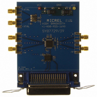
SY87739LHI-EVAL
Description
BOARD EVAL N SY87739 EXPERIMENT
Manufacturer
Micrel Inc
Specifications of SY87739LHI-EVAL
Main Purpose
Timing, Frequency Synthesizer
Embedded
No
Utilized Ic / Part
SY87739
Primary Attributes
Single Integer-N PLL
Secondary Attributes
729MHz, Graphical User Interface, PECL Inputs and Outputs, 3.3V
Lead Free Status / RoHS Status
Lead free / RoHS Compliant
Other names
576-1406
SY87739L-EVAL
SY87739L-EVAL


Micrel, Inc.
jitter of the SY87729/39L evaluation board:
set to about 3.3V. Current consumption will be between
250mA and 300mA. Connect the positive power supply to
the red or yellow banana jack, J1, labeled “V
the silk screen. Connect the negative power supply to the
black banana jack, J2, labeled “GND” under it on the silk
screen.
matched SMA patch cables to connect XTAL+ (J8) to
REFCLK+ (J3). Use the other of the two length matched
SMA patch cables to connect XTAL– (J7) to REFCLK–
(J4).
between the PC parallel port and the SY87729/39L
evaluation board’s Centronics plug, J9. Launch the download
software and verify that either the message “729 Locked,"
“729 NOT Locked” or “739 Locked," “739 NOT Locked"
appears at the upper right of the download application’s
window.
a calculation module. Enter the target frequency in the “729
Output” or “739 Output” edit box and have the calculation
module determine the configuration parameters. Have the
download module configure the SY87729/39L evaluation
board, and verify that the indicator at the upper right of the
download application is green, and that it says “729 Locked,"
or “739 Locked.”
M9999-071906
hbwhelp@micrel.com or (408) 955-1690
The following steps allow the user to verify cycle-to-cycle
1. Connect Power Source : The power supply should be
2. Connect Clock Source : Use one of the two length
3. Connect Configuration Source : Attach the printer cable
4. Configure the SY87729/39L Evaluation Board : Launch
CC
” under it on
10
that terminates into 50 . Connect a 50
CLKOUT– (J6). Measure the cycle-to-cycle jitter.
used. It measures higher jitter than what is actually produced
by the SY87729/39L evaluation board because of the single-
ended nature of the Wavecrest inputs. Alternatively, a
sampling scope with histogram capability could be used,
along with a delay line, where the signal input is the
CLKOUT+ signal and the trigger input is the CLKOUT–
signal. Also, a high-speed real-time scope may be used
with Amherst M1 jitter analysis software.
that are other than integer ratios of the input frequency,
some forms of jitter measurement cannot be taken with
certain types of test equipment. This is especially true when
using sampling (sometimes called equivalent time) scopes
to measure jitter histograms, as these require a trigger signal
separate from their input. Unless the SY87729/39L is
configured to perform an integer multiply, the trigger to the
scope can only be the complement clock output.
5. Verify Output Jitter : Connect CLKOUT+ (J5) to a TIA
In the set up of Figure 2, a Wavecrest DTS-2079 is
Because the SY87729/39L generates clock frequencies
Evaluation Board
termination to
SY87729/39L
Related parts for SY87739LHI-EVAL
Image
Part Number
Description
Manufacturer
Datasheet
Request
R

Part Number:
Description:
Manufacturer:
Micrel Inc
Datasheet:
Part Number:
Description:
Manufacturer:
Micrel Inc
Datasheet:
Part Number:
Description:
Manufacturer:
Micrel Inc
Datasheet:
Part Number:
Description:
Manufacturer:
Micrel Inc
Datasheet:
Part Number:
Description:
Manufacturer:
Micrel Inc
Datasheet:
Part Number:
Description:
Manufacturer:
Micrel Inc
Datasheet:
Part Number:
Description:
Manufacturer:
Micrel Inc
Datasheet:
Part Number:
Description:
Manufacturer:
Micrel Inc
Datasheet:
Part Number:
Description:
Manufacturer:
Micrel Inc
Datasheet:
Part Number:
Description:
Manufacturer:
Micrel Inc
Datasheet:
Part Number:
Description:
Manufacturer:
Micrel Inc
Datasheet:
Part Number:
Description:
Manufacturer:
Micrel Inc
Datasheet:
Part Number:
Description:
Manufacturer:
Micrel Inc
Datasheet:
Part Number:
Description:
Manufacturer:
Micrel Inc
Datasheet: