CDB8427 Cirrus Logic Inc, CDB8427 Datasheet - Page 4
CDB8427
Manufacturer Part Number
CDB8427
Description
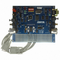
EVALUATION BOARD FOR CS8427
Manufacturer
Cirrus Logic Inc
Datasheet
1.CDB8427.pdf
(14 pages)
Specifications of CDB8427
Main Purpose
Audio, Sample Rate Converter
Embedded
Yes, MCU, 8-Bit
Utilized Ic / Part
CS8427
Primary Attributes
Sample Rate Converter with Digital Audio Transmitter and Receiver
Secondary Attributes
48 kHz Output Sample Rates, AES/EBU, S/PDIF, EIAJ-340, GUI
Product
Audio Modules
Silicon Manufacturer
Cirrus Logic
Silicon Core Number
CS8427
Kit Application Type
Communication & Networking
Application Sub Type
Digital Audio Transceiver
Kit Contents
Evaluation Board
Rohs Compliant
No
Lead Free Status / RoHS Status
Contains lead / RoHS non-compliant
Lead Free Status / RoHS Status
Lead free / RoHS Compliant, Contains lead / RoHS non-compliant
Other names
598-1783


2. CDB8427.EXE QUICK START GUIDE
2.1
Note:
1) Connect the CDB8427 to a 5 V DC power sup-
2) Set: J11 to Optical, J16 to S/PDIF, enable J13
3) Connect the CDB8427 to the PC COM port us-
4) Apply power to the board.
5) Press the RESET switch (S5).
At this point, the RERR and PROC should be lit.
The hardware is now ready!
2.2
1) Create a directory called CDB8427 anywhere
2) Copy CDB8427.exe into this directory.
3) If you do not already have them, copy the in-
4) If desired, create a shortcut to CDB8427.exe on
At this point, you are ready to start up the software.
4
ply.
(S/PDIF), and disable J15 (MUTE).
ing RS232 cable.
on your system.
cluded DLLs msvcrt.dll and mfc42.dll into
your \Windows\System directory.
your desktop.
SeeTable 1 on page 5
Setting up the Hardware
the configuration and jumper settings.
Installing the Software
and
Table 2 on page 5
for
2.3
1) Double-click on CDB8427.exe or its short-
2) If you get errors right away, the COM port
3) Click anywhere but inside one of the boxes, this
4) Select the COM port you are using to connect
5) Shut down the application, reset the board, and
2.4
1) Click anywhere but inside one of the boxes, this
2) Click on the Reset button. You should see the
3) Click on the AES3 Transmitter tab, then set the
4) Click on the Clock Sources tab, click on
5) Check the performance of the board by doing
.
cut.
needs to be set properly.
brings up the Board Setup control panel.
to the CDB8427.
then restart the application.
brings up the Board Setup control panel.
TX and RX leds light up briefly.
Transmitter data source to AES3 Receiver.
RMCK derived from AES3 input frame and un-
check the Stop Internal Clocks box.
an FFT with a -1dBFS 1kHz sine wave for in-
put at 44.1kHz and 48kHz sample rates using
the optical input and optical output.
Starting up the Software
Starting up the Hardware
CDB8427
Related parts for CDB8427
Image
Part Number
Description
Manufacturer
Datasheet
Request
R

Part Number:
Description:
Development Kit
Manufacturer:
Cirrus Logic Inc
Datasheet:
Part Number:
Description:
Development Kit
Manufacturer:
Cirrus Logic Inc
Datasheet:


Part Number:
Description:
High-efficiency PFC + Fluorescent Lamp Driver Reference Design
Manufacturer:
Cirrus Logic Inc
Datasheet:
Part Number:
Description:
Development Kit
Manufacturer:
Cirrus Logic Inc
Datasheet:
Part Number:
Description:
Development Kit
Manufacturer:
Cirrus Logic Inc
Datasheet:

Part Number:
Description:
Development Kit
Manufacturer:
Cirrus Logic Inc
Datasheet:
Part Number:
Description:
Development Kit
Manufacturer:
Cirrus Logic Inc
Datasheet:
Part Number:
Description:
Development Kit
Manufacturer:
Cirrus Logic Inc
Datasheet:
Part Number:
Description:
Development Kit
Manufacturer:
Cirrus Logic Inc
Datasheet:

Part Number:
Description:
BOARD EVAL FOR CS8416 RCVR
Manufacturer:
Cirrus Logic Inc
Datasheet:

Part Number:
Description:
EVALUATION BOARD FOR CS8420
Manufacturer:
Cirrus Logic Inc
Datasheet:

Part Number:
Description:
KIT DEVELOPMENT EP9315 ARM9
Manufacturer:
Cirrus Logic Inc
Datasheet:

Part Number:
Description:
KIT DEVELOPMENT EP9302 ARM9
Manufacturer:
Cirrus Logic Inc
Datasheet:

Part Number:
Description:
KIT DEVELOPMENT EP9307 ARM9
Manufacturer:
Cirrus Logic Inc
Datasheet: