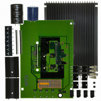
INTRODUCTION
of PWM circuits using the MSA240KC/260KC pin out. With
ample bread boarding areas it is flexible enough to analyze
a multitude of standard or proprietary circuit configurations.
Critical connections for power supply bypassing are pre-wired.
Components not usually readily available in engineering labs
are provided. External connection to the evaluation kit can be
made via the terminal block and banana jacks at the edges
of the circuit board.
BEFORE YOU GET STARTED
• All A pex Precision Power amplifiers should be handled using
• Do not change connections while the circuit is powered.
• Initially set all power supplies to the minimum operating
PARTS LIST
Ref
NA
NA
NA
NA
NA
BJ1-4
C1,3
For identification note this capacitor has “legs” .
C2*
C2*
TS1
R1,2*
R1,2*
R1,2*
*Chosen per directions
ASSEMBLY
product you are using, either the MSA240KC or MSA260KC.
1. Note that each side of the circuit board is identified as either
EK56U
This easy-to-use kit provides a platform for the evaluation
During assembly refer to Figure 1 and the data sheet for the
proper ESD precautions.
voltage allowed in the device data sheet.
the component side or "DUT side".
Evaluation Kit for MSA240KC and MSA260KC
http://www.cirrus.com
Apex Part No.
HS28
HS26
MS11
EVAL56
60SPG00004
BJ1
ZX7R105KTL
EC05
EC06
TS02
CSR22
CSR20
CSR21
EK56 MSA240, MSA260
P r o d u c t I n n o v a t i o n F r o m
P r o d u c t I n n o v a t i o n F r o m
Description/Vendor
Heat Sink,
Apex Precision Power
Heat Sink,
Apex Precision Power
30-pin socket carrier strip
PC Board
Spacer Grommets/
Micro Plastics
Banana Jack/
Deltron 164-6218
1uf 500V Cap/
Novacap
ST2225B105K501LLXW
2200uF 100V/
United Chemi-Con
82DA222M100KC2D
470uF 450V/
United Chemi-Con
KMH450VN471M35X50T2
Terminal Strip
0.020Ω Resistor/
Isotek PBV-R020-1
0.010Ω Resistor/
Isotek PBV-R010-1
0.015Ω Resistor/2
Isotek PBV-R015-1
Copyright © Cirrus Logic, Inc. 2009
(All Rights Reserved)
Qty
2
1
2
1
4
4
2
1
1
1
2
2
2. Two 30-pin socket strips have been supplied with this kit
3. Solder the surface mount capacitors at C1 and C3 on the
4. From the "component side" mount banana jacks at BJ1-4
5. Several low ohm value resistors are provided with this evalu-
6. From the "component side" of the PCB mount the HS28
7. Apply a thin layer of thermal grease on the back of the
8. Mount the remaining HS28 heat sink similarly to step 6.
9. Repeat step 7 for R1 and the second HS28 heat sink.
10. Mount the electrolytic capacitor at C2 from the "compo-
11. Mount the terminal strip to the "component side" of the
12. Mount a BNC connector (not supplied) to the PCB at loca-
13. Mount other components to complete your application
It is therefore convenient to use 3 resistors of equal value
that have been loaded with cage jacks. Using wire cutters
trim the carrier to remove two sockets from one of the strips.
Insert the socket strips from the "DUT side" of the board and
solder the jacks from the "component side" of the board,
making sure that each socket strip is fully seated before
soldering. After soldering the jacks remove and discard
the plastic carrier.
"component side" of the board.
and solder from the "DUT Side" of the circuit board. Cut
off excess lead lengths. Note that BJ1 is connected to SIG
GND.
ation kit: 0.020Ω, 0.015Ω and 0.010Ω. These are used to
implement current limiting in the output circuit. Select the
value most appropriate for your application. Refer to the
product data sheet to determine which resistor value you
should use.
heat sink closest to C2 (to be added later) and solder the
mounting tabs of the heat sink from the "DUT side" with a
high capacity soldering iron.
chosen current limiting sense resistor R2 and insert the
resistor into the PCB. Mount the resistor to the HS28 heat
sink using #4 screw and nut hardware (not supplied). Place
the screw into the mounting hole from the narrow-channel
side of the heat sink and place the nut on the screw from
the wide-channel side of the heat sink. Do not over tighten
the screw. Finally, solder the resistor terminals to the PCB
and cut off the excess lead length.
nent side" of the PCB. Match the polarity markings on the
capacitor with the polarity markings on the PCB. Use the
correct voltage capacitors for the product you are using:
A 100V capacitor for the MSA240KC, or a 450V capacitor
for the MSA260KC. Be sure the capacitors have snapped
into the PCB and solder from the "DUT side" of the PCB.
Be sure to fill the holes with solder.
PCB. Make sure the terminal strip is fully seated and solder
the pins from the "DUT side" of the PCB. Be sure to fill the
mounting holes with solder.
tion 5 (near the banana jacks) if desired. The body of the
BNC connector is tied to SIG GND.
circuit using the pads and holes provided. Refer to the data
sheet for your model and note on page 4 that:
and make up R
the PCB locations for R
RAMP
R
RAMP
from two of those resistors. Note on
RAMP1
= 2 X R
and R
OSC
APEX − EK56UREVJ
RAMP2
to do this.
EK56
MAY 2009
EK56
1