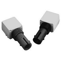
HFBR-0310 Avago Technologies US Inc., HFBR-0310 Datasheet - Page 7

HFBR-0310
Manufacturer Part Number
HFBR-0310
Description
KIT EVAL FIBER OPTIC 155MBD
Manufacturer
Avago Technologies US Inc.
Datasheet
1.HFBR-0310.pdf
(8 pages)
Specifications of HFBR-0310
Main Purpose
Interface, Fiber Optics
Embedded
No
Utilized Ic / Part
HFBR-1312T, HFBR-2316T
Primary Attributes
1300nm, 155MBd, 1x9 PECL
Secondary Attributes
62.5/125µm and 50/125µm Fiber Compatible
Kit Contents
TX/RX Mods, Cable, Pol Kit, SW, Pwr. Sup
Tool / Board Applications
Fiber Optic Transceivers
Mcu Supported Families
HFBR-1312T, HFBR-2316T
Lead Free Status / RoHS Status
Contains lead / RoHS non-compliant
Other names
516-2136
HFBR-0310
HFBR-0310
Available stocks
Company
Part Number
Manufacturer
Quantity
Price
Company:
Part Number:
HFBR-0310Z
Manufacturer:
AVAGO
Quantity:
101
Notes:
10. Percent overshoot is defined as: ((V
11. The bandwidth*risetime product is typically 0.41 because the HFBR-2316TZ has a second-order bandwidth limiting characteristic.
100 pF
Figure 1. HFBR-2316T receiver test circuit.
Figure 3. Typical pulse width distortion vs.
peak input power.
7
*Mini-Circuits Division of Components Corporation.
1. 2.0 mm from where leads enter case.
2. The signal output is referred to V
3. Typical specifications are for operation at T
4. The test circuit layout should be in accordance with good high frequency circuit design techniques.
5. Measured with a 9-pole “brick wall” low-pass filter [Mini-Circuits
6. -11.0 dBm is the maximum peak input optical power for which pulse-width distortion is less than 1 ns.
7. Electrical bandwidth is the frequency where the responsivity is -3 dB (electrical) below the responsivity measured at 50 MHz.
8. The specifled rise and fall times are referenced to a fast square wave optical source. Rise and fall times measured using an LED optical source
9. 10 ns pulse width, 50% duty cycle, at the 50% amplitude point of the waveform.
3.0
2.5
2.0
1.5
1.0
0.5
The recommended power supply is +5 V on V
minimize power supply noise.
with a 2.0 ns rise and fall time (such as the HFBR-1312T) will be approximately 0.6 ns longer than the specifled rise and fall times.
E.g.: measured t
0
0
HFBR-2316TZ
P
R
20
– INPUT OPTICAL POWER – µW
0.1 µF
10
40
r,f
~ [(specifled t
V
6
CC
3, 7
V
60
EE
= 0 V
V
= -5 V
2
O
80
<
TEST
LOAD
– 5 pF
r,f
CC
100
500
)
2
, and does not reject noise from the V
PK
+ (test source optical t
- V
120
V
100%
500
EE
100 pF
A
= -5 V
= 25 C and V
CC
)/V
Figure 4. Typical rise and fall times vs.
temperature.
for typical usage with +5 V ECL logic. A -5 V power supply on V
1 GHz FET PROBE
100%
6.0
5.0
4.0
3.0
2.0
1.0
) x 100% . The overshoot is typically 2% with an input optical rise time 1.5 ns.
-60
CC
r,f
0.1 µF
-40
= +5 V
)
2
t
t
]
f
r
1/2
-20
TM
.
TEMPERATURE – °C
DC
, BLP-100*] with -3 dB bandwidth of 100 MHz.
.
0
CC
20
power supply. Consequently, the V
40
60
80
100
Figure 2. Typical output spectral noise
density vs. frequency.
Figure 5. Normalized receiver spectral
response.
150
125
100
1.1
1.0
0.9
0.8
0.7
0.6
0.5
0.4
0.3
0.2
0.1
75
50
25
0
900 1000 1100 1200 1300 1400
0
CC
EE
power supply must be filtered.
50
is used for test purposes to
– WAVELENGTH – nm
FREQUENCY – MH
100
150
200
1500
Z
250
1600 1700
300


