801-6211-0 Enhanced Video Devices Inc, 801-6211-0 Datasheet - Page 5
801-6211-0
Manufacturer Part Number
801-6211-0
Description
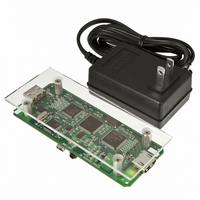
DEVELOPMENT KIT DKD-DIGITAL
Manufacturer
Enhanced Video Devices Inc
Datasheet
1.801-6211-0.pdf
(6 pages)
Specifications of 801-6211-0
Main Purpose
Video, Video Enhancement
Embedded
No
Utilized Ic / Part
312-1000-0 (EVD1000)
Primary Attributes
HDMI/DVI Inputs and Outputs, 3 levels of Enhancement, 1080i
Secondary Attributes
3 Display Modes: Full Screen, Split Screen, and Bypass. Customize via USB GUI
Lead Free Status / RoHS Status
Not applicable / Not applicable
Other names
868-1001


User-customizable Presets
The EVD application also includes a mechanism whereby parameter settings as defined on the slider
panel may be stored into the three presets on the Demonstrator board, for later use with the board in
stand-alone mode (without USB connection). This allows a customer to configure the board with
enhancement capability of their own choosing, tailored for a specific application, and then, for
example, send it out for operation in the field in compact form without the need for additional ancillary
equipment. The customizable preset capability on the Demonstrator boards can also be accessed
directly via the USB interface. The use of these features is also described in detail in an additional
Application Note.
Circuit Implementation
The block diagram below is representative of the Demonstrator board, and also provides a simple
example application for use in other existing systems. It shows all of the possible major commonly
used inputs/outputs of the EVD1000, but highlights the very simple basic connections required for
operation in this mode.
Here, video input and output for the EVD1000 is shown as YCrCb 4:2:2 digital data with embedded
SAV and EAV codes (hence the use of blanking/sync inputs/outputs are not required). The standard
receiver and transmitter handle the conversion to/from HDMI/DVI video signals which are in this case
external to the board. Note that in this mode, the video data clock for all components on the board is
derived from the input data stream by the HDMI receive r. As can be seen from the diagram, this is a
particularly simple and easy-to-implement connection scheme, although the use of the EVD1000 with
© 2009 Enhanced Video Devices, Inc. DKD-HDMI Rev 1.1 6/29/2009
HDMI data input
User interface
HDMI_IN
SCL, SDA
USER INTERFACE
MICROCONTROLLER
HDMI RECEIVER
CRCB_DATA[9:0]
Y_DATA[9:0]
SCL, SDA
PIX_CLK
20 MHz
G_Y_IN[9:0]
R_CR_IN[9:0]
B_CB_CRCB_IN[9:0]
HBLNK_IN, VBLNK_IN
HSYNC_IN, VSYNC_IN
FIELD_IN
SCL, SDA
CLK_VIDEO
CLK_SYSTEM
VCC_BUF
+3.3V
(128 pin TQFP)
EVD1000
VSS
GND
HSYNC_OUT, VSYNC_OUT
HBLNK_OUT, VBLNK_OUT
User’s Guide, EVD1000 Developer’s Kit – Digital
B_CB_CRCB_OUT[9:0]
VCC_CORE
+1.8V
R_CR_OUT[9:0]
G_Y_OUT[9:0]
FIELD_OUT
Y_DATA[9:0]
CRCB_DATA[9:0]
PIX_CLK
SCL, SDA
HDMI TRANSMITTER
HDMI_OUT
HDMI data output
Page 5
Related parts for 801-6211-0
Image
Part Number
Description
Manufacturer
Datasheet
Request
R

Part Number:
Description:
AUDIO TRANSFORMER
Manufacturer:
Hammond Manufacturing
Datasheet:

Part Number:
Description:
Conn Socket Strip SKT 36 POS 2.54mm Solder ST Thru-Hole
Manufacturer:
Precidip
Part Number:
Description:
Conn Socket Strip SKT 10 POS 2.54mm Solder ST Thru-Hole
Manufacturer:
Precidip
Part Number:
Description:
Conn Socket Strip SKT 50 POS 2.54mm Solder ST Thru-Hole
Manufacturer:
Precidip
Part Number:
Description:
Conn Socket Strip RCP 5 POS 2.54mm Solder ST Thru-Hole Box
Manufacturer:
Precidip
Part Number:
Description:
Conn Socket Strip RCP 7 POS 2.54mm Solder ST Thru-Hole Box
Manufacturer:
Precidip
Part Number:
Description:
Conn Socket Strip RCP 8 POS 2.54mm Solder ST Thru-Hole Box
Manufacturer:
Precidip
Part Number:
Description:
Conn Socket Strip RCP 10 POS 2.54mm Solder ST Thru-Hole Box
Manufacturer:
Precidip
Part Number:
Description:
Straight socket conn, low profile, single row
Manufacturer:
Precidip
Part Number:
Description:
Conn Socket Strip SKT 6 POS 2.54mm Solder ST Thru-Hole
Manufacturer:
Precidip
Part Number:
Description:
Conn Socket Strip SKT 7 POS 2.54mm Solder ST Thru-Hole
Manufacturer:
Precidip
Part Number:
Description:
Socket connectors 2,54mm, solder pin
Manufacturer:
Precidip
Part Number:
Description:
Conn Socket Strip SKT 2 POS 2.54mm Solder ST Thru-Hole
Manufacturer:
Precidip
Part Number:
Description:
Conn Socket Strip RCP 4 POS 2.54mm Solder ST Thru-Hole Box
Manufacturer:
Precidip