HFBR-0410 Avago Technologies US Inc., HFBR-0410 Datasheet - Page 18
HFBR-0410
Manufacturer Part Number
HFBR-0410
Description
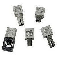
KIT EVAL FIBER OPTIC 5MBD
Manufacturer
Avago Technologies US Inc.
Specifications of HFBR-0410
Main Purpose
Interface, Fiber Optics
Embedded
No
Utilized Ic / Part
HFBR-1412, HFBR-2412
Primary Attributes
DC ~ 5MBd TTL
Secondary Attributes
ST Connectors
Silicon Core Number
HFBR-1412, HFBR-2412
Kit Contents
TX/RX Mods, Cable, Pol Kit, SW, Pwr. Sup
Silicon Family Name
HFBR-0400
Features
Dc To 5 MBd TTL Compatible Fiber Optic Component
Lead Free Status / RoHS Status
Contains lead / RoHS non-compliant
Other names
516-2138
HFBR-0410
HFBR-0410


Recommended Drive Circuits
The circuit used to supply current to the LED transmitter
can significantly influence the optical switching charac-
teristics of the LED. The optical rise/fall times and propa-
gation delays can be improved by using the appropriate
circuit techniques. The LED drive circuit shown in Figure
11 uses frequency compensation to reduce the typical
rise/fall times of the LED and a small pre-bias voltage to
minimize propagation delay differences that cause pulse-
width distortion. The circuit will typically produce rise/fall
times of 3 ns, and a total jitter including pulse-width dis-
18
R
R
R
R
C(pF)
Example
V
Y
X1
EQ2
X2
F
All HFBR-14XXZ LED transmitters are classified as IEC 825-1 Accessible Emission Limit (AEL) Class 1 based upon the current
proposed draft scheduled to go in to effect on January 1, 1997. AEL Class 1 LED devices are considered eye safe. Contact your
Avago Technologies sales representative for more information.
CAUTION: The small junction sizes inherent to the design of these components increase the components’ susceptibility to
damage from electrostatic discharge (ESD). It is advised that normal static precautions be taken in handling and assembly of
these components to prevent damage and/or degradation which may be induced by ESD.
can
(V
=
=
(
CC
R
1
Ω
2
=
X3
be
(
)
-
2000
R
3.97
=
for
V
R
=
obtained
X1
R
F
Y
R
)
(
X1
X4
I
)
Ω
+
ps
F
-
=
3.97(V
)
ON
I
F
1
3(R
ON
=
from
100mA
(A)
EQ2
CC
)
-
Figure
V
F
:
-
1.6V)
( 9
=
1.84
V)
.
tortion of less than 1 ns. This circuit is recommended for
applications requiring low edge jitter or high-speed data
transmission at signal rates of up to 155 MBd. Component
values for this circuit can be calculated for different LED
drive currents using the equations shown below. For
additional details about LED drive circuits, the reader is
encouraged to read Avago Technologies Application Bul-
letin 78 and Application Note 1038.
R
R
R
R
R
C
Y
Y
X1
EQ2
X2
=
=
=
=
=
2000
11.8
=
(5
3.16
R
1
2
11.8
X3
(
-
0.100
93.5
3.97
1.84)
Ω
ps
=
+
1 -
R
6.19
=
X4
)
=
169
+
=
=
10.8
3.97(5
=
11.8
3
0.100
pF
93.5
(10.8)
Ω
Ω
-
Ω
1.84
=
32.4
-
1.6)
Ω
Related parts for HFBR-0410
Image
Part Number
Description
Manufacturer
Datasheet
Request
R

Part Number:
Description:
Fiber Optic Transmitters, Receivers, Transceivers 1300nm 155MBd 16-pin DIP ST Rx
Manufacturer:
Avago Technologies US Inc.

Part Number:
Description:
FIBER OPTIC TX 125 MBD 650N
Manufacturer:
Avago Technologies US Inc.
Datasheet:

Part Number:
Description:
Fiber Optic Evaluation Kit
Manufacturer:
Avago Technologies US Inc.
Datasheet:

Part Number:
Description:
RECEIVER FIBER OPTIC ST 266MBD
Manufacturer:
Avago Technologies US Inc.
Datasheet:

Part Number:
Description:
RCVR OPT HI SPEED VERS LINK HORZ
Manufacturer:
Avago Technologies US Inc.
Datasheet:

Part Number:
Description:
RCVR OPT HI SPEED VERS LINK VERT
Manufacturer:
Avago Technologies US Inc.
Datasheet:

Part Number:
Description:
TXRX OPTICAL 850NM VCSEL MT-RJ
Manufacturer:
Avago Technologies US Inc.
Datasheet:

Part Number:
Description:
TXRX MM SFP LC CONN BAIL DELATCH
Manufacturer:
Avago Technologies US Inc.
Datasheet:

Part Number:
Description:
TXRX MMF SFP GBE/FC BAIL DELATCH
Manufacturer:
Avago Technologies US Inc.
Datasheet:

Part Number:
Description:
XMITTER FIBER OPTIC 266MBD ST
Manufacturer:
Avago Technologies US Inc.
Datasheet:

Part Number:
Description:
OPTOCOUPLER GATE DRV 2A 16-SOIC
Manufacturer:
Avago Technologies US Inc.
Datasheet:
Part Number:
Description:
OPTOCOUPLER 2CH 2.5A 16-SOIC
Manufacturer:
Avago Technologies US Inc.
Datasheet:

Part Number:
Description:
OPTOCOUPLER GATE DRV 0.4A 16SOIC
Manufacturer:
Avago Technologies US Inc.
Datasheet:

Part Number:
Description:
OPTOCOUPLER 2.0A 250KHZ 8-DIP
Manufacturer:
Avago Technologies US Inc.
Datasheet:

Part Number:
Description:
OPTOCOUPLER 2.0A 250KHZ GW 8-SMD
Manufacturer:
Avago Technologies US Inc.
Datasheet: