HFBR-0410 Avago Technologies US Inc., HFBR-0410 Datasheet - Page 11
HFBR-0410
Manufacturer Part Number
HFBR-0410
Description
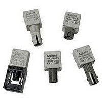
KIT EVAL FIBER OPTIC 5MBD
Manufacturer
Avago Technologies US Inc.
Specifications of HFBR-0410
Main Purpose
Interface, Fiber Optics
Embedded
No
Utilized Ic / Part
HFBR-1412, HFBR-2412
Primary Attributes
DC ~ 5MBd TTL
Secondary Attributes
ST Connectors
Silicon Core Number
HFBR-1412, HFBR-2412
Kit Contents
TX/RX Mods, Cable, Pol Kit, SW, Pwr. Sup
Silicon Family Name
HFBR-0400
Features
Dc To 5 MBd TTL Compatible Fiber Optic Component
Lead Free Status / RoHS Status
Contains lead / RoHS non-compliant
Other names
516-2138
HFBR-0410
HFBR-0410


11
Figure 3. HFBR-1414/HFBR-2412 link design
limits with 62.5/125 m cable.
Figure 6. Propagation delay through system
with one meter of cable.
Figure 8. System propagation delay test circuit and waveform timing definitions.
75
70
65
60
55
50
45
40
35
30
25
20
-22 -21 -20 -19 -18 -17 -16 -15 -14 -13 -12
P
R
– RECEIVER POWER – dBm
t
t
PLH
PHL
(TYP) @ 25°C
(TYP) @ 25°C
Figure 4. HFBR-14X2/HFBR-24X2 link design
limits with 100/140 m cable.
Figure 7. Typical distortion of pseudo random
data at 5 Mb/s.
55
50
45
40
35
30
25
20
-22 -21 -20 -19 -18 -17 -16 -15 -14 -13 -12
P
R
– RECEIVER POWER – dBm
Figure 5. HFBR-14X4/HFBR-24X2 link design
limits with 50/125 m cable.
-3
-1
-2
-4
-5
-6
0
0
0.4
WORST CASE
-40°C, +85°C
UNDERDRIVE
CABLE ATTENUATION dB/km
LINK LENGTH (km)
0.8
MAX (-40°C, +85°C)
MIN (-40°C, +85°C)
TYP (-40°C, +85°C)
1.2
TYPICAL 26°C
UNDERDRIVE
1.6
2.8
4
1
2
50
40
30
20
60
Related parts for HFBR-0410
Image
Part Number
Description
Manufacturer
Datasheet
Request
R

Part Number:
Description:
Fiber Optic Transmitters, Receivers, Transceivers 1300nm 155MBd 16-pin DIP ST Rx
Manufacturer:
Avago Technologies US Inc.

Part Number:
Description:
FIBER OPTIC TX 125 MBD 650N
Manufacturer:
Avago Technologies US Inc.
Datasheet:

Part Number:
Description:
Fiber Optic Evaluation Kit
Manufacturer:
Avago Technologies US Inc.
Datasheet:

Part Number:
Description:
RECEIVER FIBER OPTIC ST 266MBD
Manufacturer:
Avago Technologies US Inc.
Datasheet:

Part Number:
Description:
RCVR OPT HI SPEED VERS LINK HORZ
Manufacturer:
Avago Technologies US Inc.
Datasheet:

Part Number:
Description:
RCVR OPT HI SPEED VERS LINK VERT
Manufacturer:
Avago Technologies US Inc.
Datasheet:

Part Number:
Description:
TXRX OPTICAL 850NM VCSEL MT-RJ
Manufacturer:
Avago Technologies US Inc.
Datasheet:

Part Number:
Description:
TXRX MM SFP LC CONN BAIL DELATCH
Manufacturer:
Avago Technologies US Inc.
Datasheet:

Part Number:
Description:
TXRX MMF SFP GBE/FC BAIL DELATCH
Manufacturer:
Avago Technologies US Inc.
Datasheet:

Part Number:
Description:
XMITTER FIBER OPTIC 266MBD ST
Manufacturer:
Avago Technologies US Inc.
Datasheet:

Part Number:
Description:
OPTOCOUPLER GATE DRV 2A 16-SOIC
Manufacturer:
Avago Technologies US Inc.
Datasheet:
Part Number:
Description:
OPTOCOUPLER 2CH 2.5A 16-SOIC
Manufacturer:
Avago Technologies US Inc.
Datasheet:

Part Number:
Description:
OPTOCOUPLER GATE DRV 0.4A 16SOIC
Manufacturer:
Avago Technologies US Inc.
Datasheet:

Part Number:
Description:
OPTOCOUPLER 2.0A 250KHZ 8-DIP
Manufacturer:
Avago Technologies US Inc.
Datasheet:

Part Number:
Description:
OPTOCOUPLER 2.0A 250KHZ GW 8-SMD
Manufacturer:
Avago Technologies US Inc.
Datasheet: