ATWEBDVK-02WC Atmel, ATWEBDVK-02WC Datasheet - Page 117
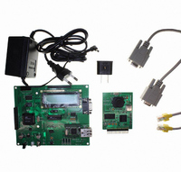
ATWEBDVK-02WC
Manufacturer Part Number
ATWEBDVK-02WC
Description
KIT DEV TCP/IP AT89C51RD2 WEBCAM
Manufacturer
Atmel
Series
@Webr
Datasheet
1.ATWEBDVK-02RC.pdf
(137 pages)
Specifications of ATWEBDVK-02WC
Main Purpose
*
Embedded
*
Utilized Ic / Part
AT89C51RD2
Primary Attributes
*
Secondary Attributes
*
Lead Free Status / RoHS Status
Contains lead / RoHS non-compliant


25.3
25.3.1
4235K–8051–05/08
AC Parameters
Explanation of the AC Symbols
Figure 25-4. Clock Signal Waveform for I
Each timing symbol has 5 characters. The first character is always a “T” (stands for time). The
other characters, depending on their positions, stand for the name of a signal or the logical sta-
tus of that signal. The following is a list of all the characters and what they stand for.
Example:T
(Load Capacitance for port 0, ALE and PSEN = 100 pF; Load Capacitance for all other outputs =
80 pF.)
Table 25-1 Table 25-4, and Table 25-7 give the description of each AC symbols.
Table
Table 25-2, Table 25-3 and Table 25-9 give the frequency derating formula of the AC parameter
for each speed range description. To calculate each AC symbols. take the x value in the corre-
ponding column (-M) and use this value in the formula.
Example: T
x = 35 ns
T 50 ns
T
CCIV
= 4T - x = 165 ns
T
25-2, Table 25-3, Table 25-5 and Table 25-8 gives the range for each AC parameter.
LLPL
AVLL
LLIU
= Time for ALE Low to PSEN Low.
= Time for Address Valid to ALE Low.
for -M and 20 MHz, Standard clock.
V
CC
T
-0.5V
0.45V
CHCL
T
CLCH
= T
CHCL
CC
Tests in Active and Idle Modes
= 5ns.
T
CLCH
0.7V
0.2V
CC
CC
-0.1
AT89C51RD2/ED2
117
Related parts for ATWEBDVK-02WC
Image
Part Number
Description
Manufacturer
Datasheet
Request
R

Part Number:
Description:
KIT DEV TCP/IP AT89C51RD2
Manufacturer:
Atmel
Datasheet:

Part Number:
Description:
KIT DEV TCP/IP AT89C51RD2 REMOTE
Manufacturer:
Atmel
Datasheet:

Part Number:
Description:
KIT DEV TCP/IP AT89C51RD2 VOIP
Manufacturer:
Atmel
Datasheet:

Part Number:
Description:
DEV KIT FOR AVR/AVR32
Manufacturer:
Atmel
Datasheet:

Part Number:
Description:
INTERVAL AND WIPE/WASH WIPER CONTROL IC WITH DELAY
Manufacturer:
ATMEL Corporation
Datasheet:
Part Number:
Description:
Low-Voltage Voice-Switched IC for Hands-Free Operation
Manufacturer:
ATMEL Corporation
Datasheet:
Part Number:
Description:
MONOLITHIC INTEGRATED FEATUREPHONE CIRCUIT
Manufacturer:
ATMEL Corporation
Datasheet:
Part Number:
Description:
AM-FM Receiver IC U4255BM-M
Manufacturer:
ATMEL Corporation
Datasheet:
Part Number:
Description:
Monolithic Integrated Feature Phone Circuit
Manufacturer:
ATMEL Corporation
Datasheet:
Part Number:
Description:
Multistandard Video-IF and Quasi Parallel Sound Processing
Manufacturer:
ATMEL Corporation
Datasheet:
Part Number:
Description:
High-performance EE PLD
Manufacturer:
ATMEL Corporation
Datasheet:
Part Number:
Description:
8-bit Flash Microcontroller
Manufacturer:
ATMEL Corporation
Datasheet: