DV251001 Microchip Technology, DV251001 Datasheet
DV251001
Specifications of DV251001
DV251001R
Available stocks


Related parts for DV251001

DV251001 Summary of contents
Page 1
... Microchip Technology Inc. M MCP2515 Development Kit User’s Guide DS51416A ...
Page 2
... Serialized Quick Turn Programming (SQTP service mark of Microchip Technology Incorporated in the U.S.A. All other trademarks mentioned herein are property of their respective companies. © 2003, Microchip Technology Incorporated, Printed in the U.S.A., All Rights Reserved. Printed on recycled paper. Microchip received QS-9000 quality system ...
Page 3
... Selecting the LPT Port .................................................................. 12 3.6 Hardware Overview ...................................................................... 13 Chapter 4. The Software Templates 4.1 Introduction ................................................................................... 15 4.2 Highlights ...................................................................................... 15 4.3 MCP2515 Register View Template ............................................... 15 4.4 Basic Template ............................................................................. 22 4.5 Menus ........................................................................................... 27 2003 Microchip Technology Inc. MCP2515 DEVELOPMENT KIT Table of Contents USER’S GUIDE DS51416A-page iii ...
Page 4
... MCP2510 Development Kit User’s Guide Chapter 5. Reconfigure the Hardware 5.1 Introduction ...................................................................................29 5.2 Highlights ......................................................................................29 5.3 Node Configurations .....................................................................29 5.4 Oscillator Configurations ...............................................................30 5.5 The Jumper Settings .....................................................................31 Appendix A. Schematics A.1 Introduction ...................................................................................33 A.2 Schematic .....................................................................................34 Appendix B. FAQs on Configuring the MCP2515 B.1 Introduction ...................................................................................37 B.2 FAQs .............................................................................................37 DS51416A-page iv 2003 Microchip Technology Inc. ...
Page 5
... The two nodes are connected via a CAN bus that is also routed off-board through a connector, allowing the target board to be connected to an external CAN bus. This node will be referred to as “node 1” throughout this document. 2003 Microchip Technology Inc. MCP2515 DEVELOPMENT KIT USER’S GUIDE ...
Page 6
... Example, node 0 could be used as a simple bus monitor (using the Basic template) in order to monitor the development of node 1 (microcontroller node). Node 0 may also be used to set/verify bit timings, masks and filters. DS51416A-page 2 2003 Microchip Technology Inc. ...
Page 7
... Kvaser web site (www.kvaser.se searching the internet for “port95nt”. The port95nt software provides drivers for I/O access. The software can be installed with the minimal configuration by selecting custom install and checking only the driver install box. 2003 Microchip Technology Inc. ® ...
Page 8
... NOTES: DS51416A-page 4 2003 Microchip Technology Inc. ...
Page 9
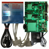
... This chapter describes the procedure for installing the MCP2515 Development Kit. 2.2 HIGHLIGHTS The items discussed in this chapter are: • MCP2515 Development Kit components • Installing the hardware • Installing the software 2003 Microchip Technology Inc. MCP2515 DEVELOPMENT KIT USER’S GUIDE DS51416A-page 5 ...
Page 10
... CD-ROM with program software, User’s Guide and other supporting documents and code samples (forthcoming) • Power cable and adapter • Microchip Technical Library CD-ROM FIGURE 2-1: DS51416A-page 6 ® MCU with demo firmware) MCP2515 DEVELOPMENT KIT COMPONENTS 2003 Microchip Technology Inc. ...
Page 11
... Browse and find the file. Alternate method: Through Win- dows Explorer the software program. Note: If installing on a Windows NT/2000/XP platform, third party drivers must be installed to allow I/O access to the parallel port. Refer to Section 1.6 “Host Computer System Requirements”. 2003 Microchip Technology Inc. 6 Not Connected 7 CANH 8 Not Connected ...
Page 12
... NOTES: DS51416A-page 8 2003 Microchip Technology Inc. ...
Page 13
... MCP2515 Register View Template This template allows low-level control of the MCP2515 and would typically be used to evaluate/test the MCP2515 at the bit level. All registers required for complete configuration are available in this template. 2003 Microchip Technology Inc. MCP2515 DEVELOPMENT KIT USER’S GUIDE DS51416A-page 9 ...
Page 14
... The transmit window controls the buffer contents for the transmit registers, including TXBnCTRL, the identifier registers and the data registers. This window contains all of the buffer contents for the receive buffers, including RXBnCTRL, the identifier registers and the data registers. Message Filter Transmit 2003 Microchip Technology Inc. ...
Page 15
... History List Timed Transmissions Message Format Window 2003 Microchip Technology Inc. Message Format BASIC TEMPLATE This window, labeled MCP2515 CAN Controller, provides several pieces of information about the status of the bus, including nominal bus loading, status of the node (on or off the bus) and bus bit rate ...
Page 16
... Select a template to open (Basic or MCP2515 Register View). 3.5 SELECTING THE LPT PORT When starting the program for the first time after installation, it may be necessary to select the proper LPT port address from the available list (Options > MCP2515...). DS51416A-page 12 2003 Microchip Technology Inc. ...
Page 17
... CAN Transceiver LED Banks RTS Buttons CAN Connector 2003 Microchip Technology Inc. The link between the MCP2515 and the PC that acts as the MCU for node0. The parallel port is used to allow the PC to communicate with MCP2515 via SPI. The communications port (COM) is connected to the PICmicro MCU sockets (USART pins) via a MAX-232 device so that serial communication is possible between the PICmicro MCU and PC ...
Page 18
... FIGURE 3-5: DS51416A-page 14 MCP2515 MCP2515 MCP2515 CAN DEVELOPMENT BOARD 2003 Microchip Technology Inc. ...
Page 19
... To modify the registers at the bit level, double-click the desired bit. The bit will toggle for each double-click and the byte representation will be reflected next to the register name. The bit boxes are only modifiable when unshaded. Shaded bit boxes are read-only bits. 2003 Microchip Technology Inc. MCP2515 DEVELOPMENT KIT USER’S GUIDE DS51416A-page 15 ...
Page 20
... The condition of the registers are also shown (e.g., CANSTAT = 80h displays the condition as Configuration mode with no interrupts pending). FIGURE 4-7: DS51416A-page 16 Physical Layer Configuration MCP2515 REGISTER VIEW TEMPLATE STATUS WINDOW Message Filter Transmit 2003 Microchip Technology Inc. ...
Page 21
... When the desired mask and filter combinations are achieved, the values can be written to the MCP2515 by clicking the Write button. Note: The masks and filters can be written only when the MCP2515 is in Configuration mode. FIGURE 4-8: 2003 Microchip Technology Inc. MESSAGE FILTER WINDOW DS51416A-page 17 ...
Page 22
... To change oscillator values, select Options > MCP2515… from the menu bar. Note: The CNF registers can be modified only when the MCP2515 is in Configuration mode and will display shaded in all other modes of operation. FIGURE 4-9: DS51416A-page 18 PHYSICAL LAYER WINDOW 2003 Microchip Technology Inc. ...
Page 23
... This register is the interrupt-enable for the eight interrupt sources. Enabled interrupts are mapped to the INT pin. 4.3.4.5 CANCTRL CANCTRL sets the modes of operation and the clock out enable and prescaler (CLKOUT pin). FIGURE 4-10: 2003 Microchip Technology Inc. CONFIGURATION WINDOW DS51416A-page 19 ...
Page 24
... Like the other register windows, the Transmit window maps the byte values to the bit boxes. Entering data into the CAN ID box maps to multiple registers (SIDH, SIDL, EID8 and EID0). Example: Entering 1FFFFFFFFh in the CAN ID box maps all ‘1s’ to SIDH, SIDL, EID8 and EID0. FIGURE 4-11: DS51416A-page 20 TRANSMIT WINDOW 2003 Microchip Technology Inc. ...
Page 25
... FIGURE 4-12: Note: Selecting Messages > MCP2515 Eval Board > Receive Buffer (or Transmit Buffer) while holding down the shift key will open up duplicate windows so multiple transmit or receive windows can be monitored simultaneously. 2003 Microchip Technology Inc. RECEIVE WINDOW DS51416A-page 21 ...
Page 26
... This template would typically be used as a simple bus monitor for evaluating the MCP2515 on a CAN bus or in assisting development by monitoring how node 1 is operating. Bus Status Timed Transmissions FIGURE 4-13: DS51416A-page 22 Message Format THE BASIC TEMPLATE Output Window History List 2003 Microchip Technology Inc. ...
Page 27
... Normal and Configuration. The Bus Parameters view allows configuration of the bus rate, the sample point, the synchronizing jump width (SJW) and switching between Normal and Listen-Only modes of operation. FIGURE 4-14: 2003 Microchip Technology Inc. BUS STATUS DS51416A-page 23 ...
Page 28
... ID. Used in conjunction with the delta time feature, the frequency of each message type can be observed. The cut and paste menu items are standard operating system features. FIGURE 4-15: DS51416A-page 24 OUTPUT WINDOW 2003 Microchip Technology Inc. ...
Page 29
... Note: The History List window works in conjunction with the Timed Transmission window. Messages can be retransmitted once or continually at defined intervals. See the Timed Transmission description for more details. FIGURE 4-16: 2003 Microchip Technology Inc. HISTORY LIST WINDOW DS51416A-page 25 ...
Page 30
... Standard Text format can be changed by pressing the Properties button while highlighted. The properties are the numeric base and whether or not to display the message time stamp as a running total delta. FIGURE 4-18: DS51416A-page 26 TIMED TRANSMISSION WINDOW MESSAGE FORMATS WINDOW 2003 Microchip Technology Inc. ...
Page 31
... Note: The oscillator frequency must be set in software to match the hardware so the software can configure the bit timing registers correctly. The formulas for bit timing contain an oscillator frequency. FIGURE 4-19: 2003 Microchip Technology Inc. MENU BAR DS51416A-page 27 ...
Page 32
... NOTES: DS51416A-page 28 2003 Microchip Technology Inc. ...
Page 33
... CAN bus because no CAN communication occurs. This configuration is used for evaluation of, or familiarization with, the MCP2515. The Register template would be used. The masks, filters and register functions can easily be evaluated in this configuration. 2003 Microchip Technology Inc. MCP2515 DEVELOPMENT KIT USER’S GUIDE DS51416A-page 29 ...
Page 34
... This could have catastrophic results possible for each node and the microcontrollers to have their own oscillator by configuring the jumpers as described later in this chapter. DS51416A-page 30 ® 2003 Microchip Technology Inc. ...
Page 35
... Connects 120 ohm terminating resister to the CAN bus † These jumpers are provided to disconnect the MCP2551 device from the bus so other physical layers can be used, including a third-party daughter card available from Kvaser AB. 2003 Microchip Technology Inc. ™ AB for more information JUMPER DESCRIPTION ...
Page 36
... FIGURE 5-20: DS51416A-page 32 JUMPER LOCATIONS 2003 Microchip Technology Inc. ...
Page 37
... M Appendix A. Schematics A.1 INTRODUCTION This section contains schematics, which are also available on the included CD-ROM. 2003 Microchip Technology Inc. MCP2515 DEVELOPMENT KIT USER’S GUIDE DS51416A-page 33 ...
Page 38
... A.2 SCHEMATIC Note: This schematic is available on the included CD-ROM (03-01522r2-S1.pdf). RED RED RED 1 2 GREEN 1 2 GREEN 1 2 GREEN 1 2 GREEN GREEN RED RED RED 1 2 GREEN 1 2 GREEN 1 2 GREEN 1 2 GREEN GREEN DS51416A-page JMP2 2003 Microchip Technology Inc. ...
Page 39
... Note: This schematic is available on the included CD-ROM (03-01522r2-S2.pdf 2003 Microchip Technology Inc DS51416A-page 35 ...
Page 40
... NOTES: DS51416A-page 36 2003 Microchip Technology Inc. ...
Page 41
... Reset MCP2515 on Open is deselected, causing the old register contents (masks and filters) to remain unchanged when switching templates. Press reset, or select the Reset MCP2515 on Open box and reopen the template. 2003 Microchip Technology Inc. MCP2515 DEVELOPMENT KIT COMMON BUS COMMUNICATION PROBLEMS Basic template – Bus button in the “ ...
Page 42
... How do I enter extended IDs into a field? Lead off the number with an ‘x’, which indicates extended frame (e.g., x12345). 6. Are there daughter boards available that change the physical layer? Yes. Contact Kvaser AB for details (www.kvaser.se). DS51416A-page 38 2003 Microchip Technology Inc. ...
Page 43
... NOTES: 2003 Microchip Technology Inc. DS51416A-page 39 ...
Page 44
... Via Quasimodo, 12 20025 Legnano (MI) Milan, Italy Tel: 39-0331-742611 Fax: 39-0331-466781 Netherlands Biesbosch 14 NL-5152 SC Drunen, Netherlands Tel: 31-416-690399 Fax: 31-416-690340 United Kingdom 505 Eskdale Road Winnersh Triangle Wokingham Berkshire, England RG41 5TU Tel: 44-118-921-5869 Fax: 44-118-921-5820 07/28/03 2003 Microchip Technology Inc. ...