AT89STK-05 Atmel, AT89STK-05 Datasheet - Page 9
AT89STK-05
Manufacturer Part Number
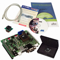
AT89STK-05
Description
KIT STARTER FOR AT89C5131
Manufacturer
Atmel
Specifications of AT89STK-05
Main Purpose
*
Embedded
*
Utilized Ic / Part
AT89C5131
Primary Attributes
*
Secondary Attributes
*
Processor To Be Evaluated
AT89C5131A
Interface Type
RS-232, USB
Lead Free Status / RoHS Status
Contains lead / RoHS non-compliant


2.4.3
2.4.4
2.4.5
AT89C5131A Starter Kit Hardware User Guide
TWI Peripheral
SPI Peripheral
LED Controller
The CT3 and CT5 contacts have to be soldered in order to use the SDA and SCL alter-
nate P4.1 and P4.0 port configuration on the SPI connector (J4).
In order to use these signals on the J5 extension connector (SDA and SCL), the CT4
and CT6 contacts have to also be soldered.
The AT89C5131A controller includes an LED controller on:
The on board LEDs can be controlled with the AT89C5131A if the corresponding con-
tacts CT9, CT10, CT11 and CT12 are bypassed.
Figure 2-6. On-board LEDs for LED Controller
– P3.3 (LED 0)
– P3.5 (LED 1)
– P3.6 (LED 2)
– P3.7 (LED 3)
LED 0
LED 1
LED 2
LED 3
0
1
2
3
LED
CT9
CT10
CT11
CT12
Hardware Description
4245A–USB–11/04
2-7
Related parts for AT89STK-05
Image
Part Number
Description
Manufacturer
Datasheet
Request
R

Part Number:
Description:
KIT EVAL APPL MASS STORAGE
Manufacturer:
Atmel
Datasheet:

Part Number:
Description:
KIT DEMOBOARD 8051 MCU W/CAN
Manufacturer:
Atmel
Datasheet:

Part Number:
Description:
KIT STARTER FOR AT83C24
Manufacturer:
Atmel
Datasheet:

Part Number:
Description:
EVAL BOARD FOR AT83C26
Manufacturer:
Atmel
Datasheet:

Part Number:
Description:
KIT STARTER FOR MCU AT8XC5122/23
Manufacturer:
Atmel
Datasheet:

Part Number:
Description:
KIT STARTER FOR AT89C51RX2
Manufacturer:
Atmel
Datasheet:


Part Number:
Description:
8-Bit Microcontroller with 4K Bytes Flash
Manufacturer:
ATMEL Corporation
Datasheet:

Part Number:
Description:
DEV KIT FOR AVR/AVR32
Manufacturer:
Atmel
Datasheet:
Part Number:
Description:
INTERVAL AND WIPE/WASH WIPER CONTROL IC WITH DELAY
Manufacturer:
ATMEL Corporation
Datasheet:
Part Number:
Description:
Low-Voltage Voice-Switched IC for Hands-Free Operation
Manufacturer:
ATMEL Corporation
Datasheet:
Part Number:
Description:
MONOLITHIC INTEGRATED FEATUREPHONE CIRCUIT
Manufacturer:
ATMEL Corporation
Datasheet:
Part Number:
Description:
AM-FM Receiver IC U4255BM-M
Manufacturer:
ATMEL Corporation
Datasheet:
Part Number:
Description:
Monolithic Integrated Feature Phone Circuit
Manufacturer:
ATMEL Corporation
Datasheet: