DM330022 Microchip Technology, DM330022 Datasheet - Page 15
DM330022
Manufacturer Part Number
DM330022
Description
BOARD DEV DSPICDEM MCSM
Manufacturer
Microchip Technology
Series
dsPIC™r
Datasheet
1.DM330022.pdf
(38 pages)
Specifications of DM330022
Main Purpose
Power Management, Motor Control
Embedded
*
Utilized Ic / Part
Stepper Motors
Primary Attributes
*
Secondary Attributes
*
Processor To Be Evaluated
dsPICDEM
Processor Series
dsPIC DSC
Interface Type
USB, UART
Operating Supply Voltage
15 V
Lead Free Status / RoHS Status
Lead free / RoHS Compliant
Lead Free Status / RoHS Status
Lead free / RoHS Compliant, Lead free / RoHS Compliant
Available stocks
Company
Part Number
Manufacturer
Quantity
Price
Company:

Part Number:
DM330022
Manufacturer:
MICROCHIP
Quantity:
12 000


2.1
TABLE 2-1:
© 2009 Microchip Technology Inc.
J8 Pin Number
J8 Pin Name
BOARD SETUP
1
2
3
4
5
6
7
8
MOTOR CONFIGURATION TABLE
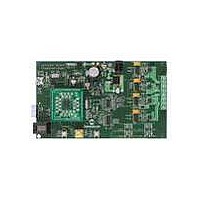
This chapter describes how to set up the dsPICDEM MCSM Development Board
hardware and software; and how to run the included demonstration software. Refer to
Chapter 3. “Hardware” for detailed information on the board and its components.
Topics in this chapter include:
• Board Setup
• Programming and Debugging Application Code
The following procedure describes how to set up the dsPICDEM MCSM Development
Board to run with the demonstration software. The stepper motor used for the
demonstration is the Leadshine Stepping Motor (P/N 42HS03).
1. Place the dsPICDEM MCSM Development Board on a sturdy insulated platform.
2. Make sure that the dsPIC33FJ32MC204 device or an appropriate PIM is
3. Connect the stepper motor (42HS03) to J8. Connect the motor phases in a bipo-
The
per motors. Before connecting the motor, make sure that the power rating of the motor
is equal to or less than the power rating of the board, as shown in Appendix
B. “Electrical Specifications”. Also, make sure the configuration resistors are correct
for the firmware and the specific dsPIC DSC device mounted on the socket. Failure to
comply with this warning could lead to malfunction of the board and the motor, and
could result in physical harm.
Before beginning the start-up procedure, complete a visual check of the board and the
motor for connectivity and mechanical damage. If damage is found, DO NOT power-up
the board. Otherwise, you may further damage the equipment. Contact Microchip’s
local office or distributor immediately.
NC
M1
DC+
M2
M3
DC+
M4
NC
mounted in the respective socket.
lar series connection as described in Table 2-1.
ds
Bipolar
Series
PICDEM MCSM Development Board is intended to drive bipolar or unipolar step-
Chapter 2. Getting Started
Green+Yellow
Black
Orange
Red
Brown
Blue+White
Bipolar Parallel
—
—
Black+Yellow
Green+Orange
Red+White
Blue+Brown
Bipolar Half-winding
WARNING
DEVELOPMENT BOARD
—
—
—
—
dsPICDEM™ MCSM
USER’S GUIDE
Yellow
Black
Orange
Green
Red
White
Blue
Brown
Unipolar
DS70610A-page 15
Black
Green+Yellow
Orange
Red
Blue+White
Brown
—
—
Related parts for DM330022
Image
Part Number
Description
Manufacturer
Datasheet
Request
R

Part Number:
Description:
Manufacturer:
Microchip Technology Inc.
Datasheet:
Part Number:
Description:
Manufacturer:
Microchip Technology Inc.
Datasheet:
Part Number:
Description:
Manufacturer:
Microchip Technology Inc.
Datasheet:
Part Number:
Description:
Manufacturer:
Microchip Technology Inc.
Datasheet:
Part Number:
Description:
Manufacturer:
Microchip Technology Inc.
Datasheet:
Part Number:
Description:
Manufacturer:
Microchip Technology Inc.
Datasheet:
Part Number:
Description:
Manufacturer:
Microchip Technology Inc.
Datasheet:
Part Number:
Description:
Manufacturer:
Microchip Technology Inc.
Datasheet: