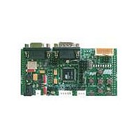
ATDVK90CAN1 Atmel, ATDVK90CAN1 Datasheet - Page 36
ATDVK90CAN1
Manufacturer Part Number
ATDVK90CAN1
Description
KIT DEV FOR AT90CAN128 MCU
Manufacturer
Atmel
Specifications of ATDVK90CAN1
Main Purpose
*
Embedded
*
Utilized Ic / Part
AT90CAN AVR Devices
Primary Attributes
*
Secondary Attributes
*
Processor To Be Evaluated
AT90CAN
Data Bus Width
8 bit
Interface Type
RS-232, SPI, TWI
Core Architecture
AVR
Core Sub-architecture
AVR UC3
Kit Contents
Board, AT90CAN128 Sample Microcontroller, 9V Battery Power Cable, CD-ROM, Manuals
Features
RS232, CAN, LIN, SPI & TWI Serial Interface
Rohs Compliant
Yes
Lead Free Status / RoHS Status
Contains lead / RoHS non-compliant
Available stocks
Company
Part Number
Manufacturer
Quantity
Price
Company:

Part Number:
ATDVK90CAN1
Manufacturer:
Atmel
Quantity:
135


3.8.1
3.8.2
3.8.3
3.8.4
DVK90CAN1 Hardware User Guide
Supply Voltage from STK500
Analog Reference Voltage from STK500
EXP.CON 0 & EXP.CON 1 Connectors
Main Clock from STK500
The AVR supply voltage coming from STK500 (VTG) can also be controlled from AVR
Studio®.
The AVR Analog Reference Voltage coming from STK500 (REF) can also be controlled
from AVR Studio®.
Figure 3-41 . EXP.CON 0 and EXP.CON 1 Connectors
The AVR clock frequency (external) coming from STK500 (XT1/XT2) can also be
controlled from AVR Studio®.
Need of the optional expended connectors EXP.CON 0 & EXP.CON 1 (J13 & J14),
Need of the optional specific decoupling capacitors (C14 & C15 = 100 nF),
The supply voltage coming from STK500 is controlled by power supply circuitry of
the DVK90CAN1. Refer to Table 3-1 . Power Supply (1) Setting to configure.
Need of the optional expended connectors EXP.CON 0 & EXP.CON 1 (J13 & J14),
Need of the optional specific decoupling capacitor (C16 = 100 nF),
Refer to Table 3-5 . ANA REF Setting to configure.
Need of the optional expended connectors EXP.CON 0 & EXP.CON 1 (J13 & J14),
Refer to Table 3-2 . Main Clock Setting to configure XTAL1 & XTAL2.
n.c. (AUXI0)
n.c. (CT7)
n.c. (CT5)
n.c. (CT3)
n.c. (CT1)
NRST
GND
GND
GND
PG1
VTG
PC7
PC5
PC3
PC1
PA7
PA5
PA3
PA1
n.c.
EXP. CON 0
13 14
15 16
17 18
19 20
21 22
23 24
25 26
27 28
29 30
31 32
33 34
35 36
37 38
39 40
11 12
1 2
3 4
5 6
7 8
9 10
GND
n.c. (AUXO0)
n.c. (CT6)
n.c. (CT4)
n.c. (CT2)
n.c. (BSEL2)
REF
PG2
PG0
GND
VTG
PC6
PC4
PC2
PC0
PA6
PA4
PA2
PA0
GND
Top View
n.c. (DATA7)
n.c. (DATA5)
n.c. (DATA3)
n.c. (DATA1)
n.c. (AUXI1)
n.c. (SCK)
n.c. (SI)
GND
GND
GND
VTG
PB7
PB5
PB3
PB1
PD7
PD5
PD3
PD1
XT1
EXP. CON 1
13 14
15 16
17 18
19 20
21 22
23 24
25 26
27 28
29 30
31 32
33 34
35 36
37 38
39 40
11 12
1 2
3 4
5 6
7 8
9 10
GND
n.c. (AUXO1)
n.c. (DATA6)
n.c. (DATA4)
n.c. (DATA2)
n.c. (DATA0)
n.c. (SO)
n.c. (CS)
XT2
VTG
GND
PB6
PB4
PB2
PB0
PD6
PD4
PD2
PD0
GND
Using the DVK90CAN1
4381B–AVR–07/08
3-35
Related parts for ATDVK90CAN1
Image
Part Number
Description
Manufacturer
Datasheet
Request
R

Part Number:
Description:
DEV KIT FOR AVR/AVR32
Manufacturer:
Atmel
Datasheet:

Part Number:
Description:
INTERVAL AND WIPE/WASH WIPER CONTROL IC WITH DELAY
Manufacturer:
ATMEL Corporation
Datasheet:
Part Number:
Description:
Low-Voltage Voice-Switched IC for Hands-Free Operation
Manufacturer:
ATMEL Corporation
Datasheet:
Part Number:
Description:
MONOLITHIC INTEGRATED FEATUREPHONE CIRCUIT
Manufacturer:
ATMEL Corporation
Datasheet:
Part Number:
Description:
AM-FM Receiver IC U4255BM-M
Manufacturer:
ATMEL Corporation
Datasheet:
Part Number:
Description:
Monolithic Integrated Feature Phone Circuit
Manufacturer:
ATMEL Corporation
Datasheet:
Part Number:
Description:
Multistandard Video-IF and Quasi Parallel Sound Processing
Manufacturer:
ATMEL Corporation
Datasheet:
Part Number:
Description:
High-performance EE PLD
Manufacturer:
ATMEL Corporation
Datasheet:
Part Number:
Description:
8-bit Flash Microcontroller
Manufacturer:
ATMEL Corporation
Datasheet:
Part Number:
Description:
2-Wire Serial EEPROM
Manufacturer:
ATMEL Corporation
Datasheet: