ATAVRDB101 Atmel, ATAVRDB101 Datasheet - Page 3
ATAVRDB101
Manufacturer Part Number
ATAVRDB101
Description
MODULE DISPLAY LCD/RGB BACKLIGHT
Manufacturer
Atmel
Series
AVR®r
Datasheet
1.ATAVRDB101.pdf
(10 pages)
Specifications of ATAVRDB101
Main Purpose
Displays, LCD Controller
Embedded
Yes, MCU, 8-Bit
Utilized Ic / Part
ATmega1281
Primary Attributes
128x64 Pixel, RGB Backlight, Joystick
Secondary Attributes
UART (RS-232), SPI and TWI, Dataflash, Piezo Speaker
Processor To Be Evaluated
ATmega1281
Data Bus Width
8 bit
Interface Type
SPI, TWI, UART
Lead Free Status / RoHS Status
Lead free / RoHS Compliant
Available stocks
Company
Part Number
Manufacturer
Quantity
Price
Company:

Part Number:
ATAVRDB101
Manufacturer:
Atmel
Quantity:
135


2.1 AVR microcontroller
2.2 LCD display
2.3 Joystick
2.4 Piezo speaker
2.5 Power supply - battery
8073B-AVR-09/07
The LCD is controlled by an ATmega1281, which has 64 pins, 128kB of Flash
memory and 8kB of SRAM. The AVR is running from external 7.37MHz ceramic
resonator. The system clock can be scaled down internally to reduce power
consumption.
DB101 features a Display Tech, 128x64 pixel graphical LCD (64128 COG) with RGB
backlight. The LCD can be accessed in both parallel and serial mode. In serial mode
the LCD’s built in RAM memory can only be written to, while in parallel mode it can be
both written and read back. Therefore, to take full advantage of the LCD’s RAM the
parallel mode is used.
A four-way joystick with push button function is placed on the right-hand side of the
DB101. This allows the user to navigate in menus and make selections.
The joystick is connected to the mega1281’s port C, pins 3 through 7, and to port B
pin 4, which is connected to an external interrupt (can wake up the device from
sleep).
To allow audio feedback to the user a miniature piezo speaker is included on the
DB101.
The Piezo is connected to the mega1281 on pin 17 – OC1C, the output compare
channel C on timer 1. This makes it possible to control the sound generation using
the PWM output of OC1C.
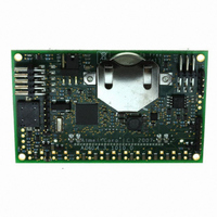
The DB101 can be powered from and external voltage source or from an on-board
coin-cell lithium battery. When running from the battery it is recommended to scale
down the system clock and not use the LCD backlight, as this can exceed the
recommended maximum current drawn from the battery. If high current is drawn from
the battery, the battery life-time can be very limited. Even with the backlight off, the
battery can be drained rather fast.
It
working/developing with the DB101.
When using external power supply the DB101 can be supplied from anywhere
between 1.8V and 5.5V. This is possible since the DB101 features a buck-boost
converter, which will provide 3.3V to the AVR and the LCD regardless of the input
voltage.
Jumper J306 controls whether the DB101 is powered from an external power source
or from the on-board battery. Shorting the jumper pins 1 and 2 will connect the battery
(default from factory), while shorting the pins 2 and 3 will connect the external supply.
is
therefore
recommended
to
connect
an
external
supply
AVR481
whenever
3
Related parts for ATAVRDB101
Image
Part Number
Description
Manufacturer
Datasheet
Request
R

Part Number:
Description:
DEV KIT FOR AVR/AVR32
Manufacturer:
Atmel
Datasheet:

Part Number:
Description:
INTERVAL AND WIPE/WASH WIPER CONTROL IC WITH DELAY
Manufacturer:
ATMEL Corporation
Datasheet:
Part Number:
Description:
Low-Voltage Voice-Switched IC for Hands-Free Operation
Manufacturer:
ATMEL Corporation
Datasheet:
Part Number:
Description:
MONOLITHIC INTEGRATED FEATUREPHONE CIRCUIT
Manufacturer:
ATMEL Corporation
Datasheet:
Part Number:
Description:
AM-FM Receiver IC U4255BM-M
Manufacturer:
ATMEL Corporation
Datasheet:
Part Number:
Description:
Monolithic Integrated Feature Phone Circuit
Manufacturer:
ATMEL Corporation
Datasheet:
Part Number:
Description:
Multistandard Video-IF and Quasi Parallel Sound Processing
Manufacturer:
ATMEL Corporation
Datasheet:
Part Number:
Description:
High-performance EE PLD
Manufacturer:
ATMEL Corporation
Datasheet:
Part Number:
Description:
8-bit Flash Microcontroller
Manufacturer:
ATMEL Corporation
Datasheet:
Part Number:
Description:
2-Wire Serial EEPROM
Manufacturer:
ATMEL Corporation
Datasheet: