MCP2140DM-TMPSNS Microchip Technology, MCP2140DM-TMPSNS Datasheet - Page 16
MCP2140DM-TMPSNS
Manufacturer Part Number
MCP2140DM-TMPSNS
Description
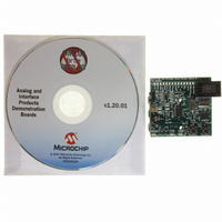
BOARD DEMO FOR MCP2140
Manufacturer
Microchip Technology
Datasheets
1.MCP2140-ISO.pdf
(58 pages)
2.MCP2140-ISO.pdf
(6 pages)
3.MCP2140DM-TMPSNS.pdf
(52 pages)
Specifications of MCP2140DM-TMPSNS
Main Purpose
Interface, IrDA
Embedded
Yes, MCU, 8-Bit
Utilized Ic / Part
MCP2140
Primary Attributes
IrDA Controller with PIC18F MCU and Temp Sensor Temp
Secondary Attributes
Set up as a Data Logger
Processor To Be Evaluated
MCP2140
Interface Type
ICSP
Silicon Manufacturer
Microchip
Silicon Core Number
MCP2140
Kit Application Type
Sensing - Temperature
Application Sub Type
Temperature Sensor
Kit Contents
Board
Rohs Compliant
Yes
Lead Free Status / RoHS Status
Lead free / RoHS Compliant
Lead Free Status / RoHS Status
Lead free / RoHS Compliant, Lead free / RoHS Compliant
Other names
MCP2140DM-TMPSNSR
MCP2140DM-TMPSNSR
MCP2140DM-TMPSNSR
Available stocks
Company
Part Number
Manufacturer
Quantity
Price
Company:

Part Number:
MCP2140DM-TMPSNS
Manufacturer:
Microchip Technology
Quantity:
135
Company:
Part Number:
MCP2140DM-TMPSNS
Manufacturer:
MICROCHIP
Quantity:
12 000


MCP2140
2.10.1
Actual maximum throughput is dependent on several
factors, including:
• Characteristics of the Primary device
• Characteristics of the MCP2140
• IrDA standard protocol overhead
The IrDA standard specifies how the data is passed
between the Primary device and Secondary device. In
IrCOMM, an additional 8 bytes are used by the protocol
for each packet transfer.
The most significant factor in data throughput is how
well the data frames are filled. If only 1 byte is sent at a
time, the throughput overhead of the IrCOMM protocol
is 89% (see
throughput is to align the amounts of data with the
receive buffer (IR and Host UART) packet size of the
MCP2140.
Then there is the delay between when data packets
are sent and received. See
of this delay (look at CTS signal falling edges). In this
screen capture, a Palm™ m105 is receiving a 240-
byte string of data from the MCP2140. When the CTS
signal goes high, the Host Controller stops sending
data (23 bytes per CTS low-time). The CTS falling
edge to CTS falling edge is approximately 90 ms (typ-
ical). This CTS high-time affects the total data through-
put. The CTS high-time will be dependant on the
characteristics of the Primary device.
TABLE 2-5:
DS21790A-page 16
MCP2140
Receive
Receive
UART
Note 1: Overhead % =
Host
IR
2: The maximum number of bytes of the IR
3: The maximum number of bytes of the
4: The CTS signal is driven high at 23 byte.
IMPROVING THROUGHPUT
(Bytes)
Packet
Receive buffer.
Host UART Receive buffer.
Size
Data
Table
64
29
23
1
1
IRCOMM OVERHEAD %
Overhead/(Overhead + Data).
2-5). The best way to maximize
Overhead
IrCOMM
(Bytes)
8
8
8
8
8
Figure 2-10
Overhead
IrCOMM
89 %
22 %
26 %
89 %
%
11 %
(1)
for an example
Comment
Note 2
Note 3
Note 4
Preliminary
2.10.1.1
The MCP2140 uses a fixed IR Receiver data block size
of 64 bytes.
The minimum size frame the Primary device can
respond with is 6 bytes.
2.10.1.2
The MCP2140 uses a fixed Host UART Receiver data
block size of 29 bytes.
2.11
An IR link can be compared to a one-wire data connec-
tion. The IR transceiver can transmit or receive, but not
both at the same time. A delay of one bit time is recom-
mended between the time a byte is received and
another byte is transmitted.
2.12
The MCP2140 has a fixed Device ID. This Device ID is
“MCP2140 xx”, with the xx indicating the silicon
revision of the device.
Turnaround Latency
Device ID
From the Primary Device
From the MCP2140
2003 Microchip Technology Inc.
Related parts for MCP2140DM-TMPSNS
Image
Part Number
Description
Manufacturer
Datasheet
Request
R

Part Number:
Description:
IC IRDA CONTROLLR DTE/DCE 18SOIC
Manufacturer:
Microchip Technology
Datasheet:

Part Number:
Description:
The MCP2140 Embeds Irda Protocol Handling And Bit Encoding/decoding, And Provides The Lowest Cost, Lowest Power Consumption Solution For Adding Irda Connectivity to Embedded Systems
Manufacturer:
Microchip Technology, Inc.
Datasheet:

Part Number:
Description:
IC IRDA CONTROLLER DTE/DCE 18DIP
Manufacturer:
Microchip Technology
Datasheet:

Part Number:
Description:
IC IRDA CONTROLLR DTE/DCE 20SSOP
Manufacturer:
Microchip Technology
Datasheet:

Part Number:
Description:
9600 BAUD FIXED SPEED IRDA PROTOCOL HANDLER & BIT ENCODER/DECODER, -40C to +85C, 20-SSOP 208mil, TUBE
Manufacturer:
Microchip Technology
Datasheet:
Part Number:
Description:
IrDA� Standard Protocol Stack Controller With Fixed 9600 Baud Communication Rate
Manufacturer:
MICROCHIP [Microchip Technology]
Datasheet:

Part Number:
Description:
Manufacturer:
Microchip Technology Inc.
Datasheet:
Part Number:
Description:
Manufacturer:
Microchip Technology Inc.
Datasheet:
Part Number:
Description:
Manufacturer:
Microchip Technology Inc.
Datasheet:
Part Number:
Description:
Manufacturer:
Microchip Technology Inc.
Datasheet:
Part Number:
Description:
Manufacturer:
Microchip Technology Inc.
Datasheet:
Part Number:
Description:
Manufacturer:
Microchip Technology Inc.
Datasheet: