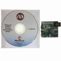
MCP2140DM-TMPSNS Microchip Technology, MCP2140DM-TMPSNS Datasheet - Page 26

MCP2140DM-TMPSNS
Manufacturer Part Number
MCP2140DM-TMPSNS
Description
BOARD DEMO FOR MCP2140
Manufacturer
Microchip Technology
Datasheets
1.MCP2140-ISO.pdf
(58 pages)
2.MCP2140-ISO.pdf
(6 pages)
3.MCP2140DM-TMPSNS.pdf
(52 pages)
Specifications of MCP2140DM-TMPSNS
Main Purpose
Interface, IrDA
Embedded
Yes, MCU, 8-Bit
Utilized Ic / Part
MCP2140
Primary Attributes
IrDA Controller with PIC18F MCU and Temp Sensor Temp
Secondary Attributes
Set up as a Data Logger
Processor To Be Evaluated
MCP2140
Interface Type
ICSP
Silicon Manufacturer
Microchip
Silicon Core Number
MCP2140
Kit Application Type
Sensing - Temperature
Application Sub Type
Temperature Sensor
Kit Contents
Board
Rohs Compliant
Yes
Lead Free Status / RoHS Status
Lead free / RoHS Compliant
Lead Free Status / RoHS Status
Lead free / RoHS Compliant, Lead free / RoHS Compliant
Other names
MCP2140DM-TMPSNSR
MCP2140DM-TMPSNSR
MCP2140DM-TMPSNSR
Available stocks
Company
Part Number
Manufacturer
Quantity
Price
Company:
Part Number:
MCP2140DM-TMPSNS
Manufacturer:
Microchip Technology
Quantity:
135
Company:
Part Number:
MCP2140DM-TMPSNS
Manufacturer:
MICROCHIP
Quantity:
12 000
MCP2140 IrDA
DS51487A-page 22
2.5.3
The MCP2140 IrDA Standard Wireless Temperature Sensor Demo Board interfaces to
the PIC18F1320 microcontroller (U1). This device was chosen for this application
because it has a UART port, an A/D Converter (ADC) for the temperature sensor
analog output, Flash memory for reprogrammability, a small footprint (package) and is
low-power.
The PIC18F1320 interfaces to the MCP2140 as described in Section 2.5.2 “MCP2140
IrDA Protocol Stack Controller Device”.
The TC1047A temperature sensor indicates the temperature by outputting an analog
signal whose magnitude corresponds to the temperature of the device. This signal is
input on analog channel AN0 (pin 1).
The MCLR input of the PIC18F1320 is connected to the RESET push button switch.
The device is reset when the RESET push button is depressed.
I/O pin RB0 is connected to the S2 push button switch. The state of the switch is polled
immediately after the device is reset (via the RESET push button), allowing the
microcontroller to determine which firmware program (“Data String Transmit” or
“Temperature Transmit)” to execute.
The PIC18F1320 is connected to a standard In-Circuit Serial Programming™ (ICSP™)
header (J1) to allow easy program access to the device.
2.5.4
The IR transceiver circuit utilizes an integrated optical transceiver. The circuit allows
any one of three devices to be used. These are:
1. Vishay
2. Vishay TFDU 4300
3. Agilent
If you wish to test with either of the other optical transceivers, the TFDU 4100 and
associated components need to be removed and the components for the desired
optical transceiver need to be installed (see the Appendix B. “Bill-Of-Materials
(BOM)”).
Figure 2-12 shows the circuit that is used to shape the waveform of the optical Trans-
ceiver’s RXD output. This is done to ensure that the RXD pulse width does not exceed
the specifications of the MCP2140 RXPD input (IR131A) (refer to Parameter IR131A
in the MCP2140 data sheet, DS21790). The resistor divider R18 and R13 sets the
RXPDREF reference threshold. Transistor Q8 (MMUN2111LT1) has internal resistors.
If you wish to evaluate a simple PNP device, Q8 can be replaced and resistors for R15
and R20 may need to be added. If R20 is added, do not forget to cut the trace that
shorts-out the resistor.
FIGURE 2-12:
®
Standard Wireless Temp Sensor Demo Board
PICmicro
IR Transceiver Circuit
®
®
TFDU 4100 (default device)
HSDL 3000
RXPDREF
RXPD
MCP2140 RXPD WAVEFORM SHAPING CIRCUIT
RXPDREF
®
Microcontroller Functions
RXPD
TP2
TP1
V
DD
R13
10 k
R18
10 k
Q6
V
R16
4.7 k
DD
R7
100
1
R15
OPT
R20
OPT
47 pF
C9
2004 Microchip Technology Inc.
RXD
(From Optical
Transceiver)


