MCP2515DM-PCTL Microchip Technology, MCP2515DM-PCTL Datasheet - Page 13
MCP2515DM-PCTL
Manufacturer Part Number
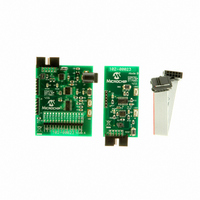
MCP2515DM-PCTL
Description
BOARD DEMO FOR MCP2515
Manufacturer
Microchip Technology
Series
PICtail™r
Type
Network Controller & Processorr
Specifications of MCP2515DM-PCTL
Main Purpose
Interface, CAN Controller
Embedded
Yes, MCU, 8-Bit
Utilized Ic / Part
MCP2515, MCP25020
Primary Attributes
Stand alone CAN Controller with CAN I/O Expander
Interface Type
CAN
Operating Voltage
5 V
Product
Modules
For Use With/related Products
MCP2515, MCP25020
Lead Free Status / RoHS Status
Contains lead / RoHS non-compliant
Secondary Attributes
-
Lead Free Status / Rohs Status
Lead free / RoHS Compliant


2.4
© 2005 Microchip Technology Inc.
FIRMWARE DESCRIPTION
See Figure 2-2 and Figure 2-3 for a simple firmware flow diagram for Node A (Node B
does not contain any firmware).
1. The firmware first configures the PIC16F676 and the MCP2515.
2. The firmware then checks a global flag bit to determine if a message needs to be
3. The firmware checks a global receive flag bit to determine if a message has been
4. The firmware loops back to #2.
FIGURE 2-2:
sent (a message containing the input button value is transmitted once every
224 ms).
2a. Node A sends a message to Node B requesting I/O status (i.e., push button
status).
received by the MCP2515. If yes, the data is read and the LED is set accordingly.
FIRMWARE FLOW DIAGRAM
ServiceIO
InitMCU
Init2515
Start
Installation and Operation
MAIN
DS51572A-page 9
Related parts for MCP2515DM-PCTL
Image
Part Number
Description
Manufacturer
Datasheet
Request
R

Part Number:
Description:
BOARD DAUGHTER PICTAIL MCP2515
Manufacturer:
Microchip Technology
Datasheet:

Part Number:
Description:
BOARD DEMO FOR MCP2515/51
Manufacturer:
Microchip Technology
Datasheet:

Part Number:
Description:
Manufacturer:
Microchip Technology Inc.
Datasheet:
Part Number:
Description:
Manufacturer:
Microchip Technology Inc.
Datasheet:
Part Number:
Description:
Manufacturer:
Microchip Technology Inc.
Datasheet:
Part Number:
Description:
Manufacturer:
Microchip Technology Inc.
Datasheet:
Part Number:
Description:
Manufacturer:
Microchip Technology Inc.
Datasheet:
Part Number:
Description:
Manufacturer:
Microchip Technology Inc.
Datasheet:
Part Number:
Description:
Manufacturer:
Microchip Technology Inc.
Datasheet:
Part Number:
Description:
Manufacturer:
Microchip Technology Inc.
Datasheet: