MCP73833EV Microchip Technology, MCP73833EV Datasheet - Page 13
MCP73833EV
Manufacturer Part Number
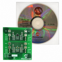
MCP73833EV
Description
BOARD EVAL FOR MCP73833
Manufacturer
Microchip Technology
Type
Battery Managementr
Specifications of MCP73833EV
Main Purpose
Power Management, Battery Charger
Embedded
No
Utilized Ic / Part
MCP7833
Primary Attributes
1 Cell- Li-Ion / Li-Pol, 4.2V @ 1A, 4.5 ~ 6 Vin
Secondary Attributes
Preconditioning, Cell Temperature Monitoring
Product
Power Management Modules
Silicon Manufacturer
Microchip
Silicon Core Number
MCP73833, MCP73834
Kit Application Type
Power Management - Battery
Application Sub Type
Battery Charger
Kit Contents
Board
Rohs Compliant
Yes
For Use With/related Products
MCP73833, MCP73834
Lead Free Status / RoHS Status
Not applicable / Not applicable
Lead Free Status / RoHS Status
Lead free / RoHS Compliant, Not applicable / Not applicable


© 2006 Microchip Technology Inc.
FIGURE 2-2:
2.3.1.3
1. As provided, the MCP73833 Li-Ion Battery Charger Evaluation Board has a fast
2. Alternatively, for the installed device, resistors R5 and R6 can be changed in
2.3.1.4
1. The MCP73833 Li-Ion Battery Charger Evaluation Board has three LED status
TABLE 2-1:
2.3.1.5
1. As provided, the installed circuit of the MCP73833 Li-Ion Battery Charger Evalu-
Shutdown
Standby
Charge in Progress
Charge Complete (EOC)
Temperature Fault
Timer Fault
System Test Mode
load will not work for preconditioning and fast charge currents. The best way to
evaluate the charge management circuit is to use a single cell Li-Ion battery
pack, or the recommended simulated battery load. Refer to
B+
charge current setting of 1A for the installed device.
order to obtain the desired fast charge current. In addition, the PROG via can be
interfaced to obtain two current settings or to utilize the PROG device enable
feature. Refer to the MCP73833/4 data sheet for choosing the appropriate value
programming resistor for the desired fast charge current.
indicators for each circuit being evaluated.
status indicators during various states of the charge cycle. ON indicates that the
respective LED is illuminated.
ation Board has the battery temperature monitor disabled. To invoke battery
temperature monitoring, an appropriate thermistor should be connected between
the THERM via and VSS via. In addition, resistors R2 and R7 should be changed
in order to obtain the desired charge inhibit window. Refer to the MCP73833/4
data sheet for choosing the appropriate resistor values.charge current monitor
for each circuit being evaluated.
B-
CHARGE CYCLE STATE
SETTING THE FAST CHARGE CURRENT
STATUS INDICATORS
BATTERY TEMPERATURE MONITOR
STATUS INDICATORS
Simulated Battery Load.
+
1,000 µF
10V Al
STAT1 (RED)
OFF
OFF
OFF
OFF
OFF
ON
ON
5Ω
10 W
Table 2-1
STAT2 (GREEN)
represents the state of the
OFF
OFF
OFF
OFF
OFF
ON
ON
Figure
+
_
Variable
Power Supply
0V - 6V
2-2.
DS51626A-page 9
PG (GREEN)
OFF
ON
ON
ON
ON
ON
ON
Related parts for MCP73833EV
Image
Part Number
Description
Manufacturer
Datasheet
Request
R

Part Number:
Description:
Manufacturer:
Microchip Technology Inc.
Datasheet:
Part Number:
Description:
Manufacturer:
Microchip Technology Inc.
Datasheet:
Part Number:
Description:
Manufacturer:
Microchip Technology Inc.
Datasheet:
Part Number:
Description:
Manufacturer:
Microchip Technology Inc.
Datasheet:
Part Number:
Description:
Manufacturer:
Microchip Technology Inc.
Datasheet:
Part Number:
Description:
Manufacturer:
Microchip Technology Inc.
Datasheet:
Part Number:
Description:
Manufacturer:
Microchip Technology Inc.
Datasheet:
Part Number:
Description:
Manufacturer:
Microchip Technology Inc.
Datasheet: