MM232R FTDI, Future Technology Devices International Ltd, MM232R Datasheet - Page 11
MM232R
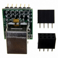
Manufacturer Part Number
MM232R
Description
MODULE MINI DEVELOPMENT FT232RQ
Manufacturer
FTDI, Future Technology Devices International Ltd
Datasheet
1.MM232R.pdf
(24 pages)
Specifications of MM232R
Main Purpose
Interface, USB 2.0 to UART (RS232/RS422/RS485) Bridge
Embedded
No
Utilized Ic / Part
FT232R
Primary Attributes
Full Speed, Rates of 300 ~ 3 MBaud, Security ID Number
Secondary Attributes
6 ~ 48MHz Clock Generator Output, Royalty-Free Drivers
Lead Free Status / RoHS Status
Lead free / RoHS Compliant
Other names
768-1021


4.3 CBUS Signal Options
The following options can be configured on the CBUS I/O pins. These options are all configured in the
internal EEPROM using the utility software FT_PROG, which can be downloaded from the www.ftdichip.com.
The default configuration is described in
CBUS Signal
Option
TXDEN#
PWREN#
TXLED#
RXLED#
TX&RXLED#
SLEEP#
CLK48
CLK24
CLK12
CLK6
CBitBangI/O
BitBangWRn
BitBangRDn
Table 4.2 CBUS Signal Options
© Copyright 2010 Future Technology Devices International Ltd
Available On CBUS Pin
CBUS0, CBUS1, CBUS2, CBUS3,
CBUS4
CBUS0, CBUS1, CBUS2, CBUS3,
CBUS4
CBUS0, CBUS1, CBUS2, CBUS3,
CBUS4
CBUS0, CBUS1, CBUS2, CBUS3,
CBUS4
CBUS0, CBUS1, CBUS2, CBUS3,
CBUS4
CBUS0, CBUS1, CBUS2, CBUS3,
CBUS4
CBUS0, CBUS1, CBUS2, CBUS3,
CBUS4
CBUS0, CBUS1, CBUS2, CBUS3,
CBUS4
CBUS0, CBUS1, CBUS2, CBUS3,
CBUS4
CBUS0, CBUS1, CBUS2, CBUS3,
CBUS4
CBUS0, CBUS1, CBUS2, CBUS3
CBUS0, CBUS1, CBUS2, CBUS3
CBUS0, CBUS1, CBUS2, CBUS3
MM232R USB - Serial UART Development Module Incorporating Clock Generator
Section 9
Description
Enable transmit data for RS485
Goes low after the device is configured by USB, then high
during USB suspend. Can be used to control power to
external logic in high power designs. Needs 10k pull up to
VCC.
Transmit data LED drive – pulses low when transmitting
data via USB.
Receive data LED drive – pulses low when receiving data
via USB.
LED drive – pulses low when transmitting or receiving
data via USB. See
Goes low during USB suspend mode. Typically used to
power down an external TTL to RS232 level converter I.C.
in USB to RS232 converter designs.
48MHz Clock output.
24 MHz Clock output.
12 MHz Clock output.
6 MHz Clock output.
CBUS bit bang mode option. Allows up to 4 of the CBUS
pins to be used as general purpose I/O. Configured
individually for CBUS0, CBUS1, CBUS2 and CBUS3 in the
internal EEPROM. A separate application note describes in
more detail how to use CBUS bit bang mode.
(www.ftdichip.com)
Synchronous and asynchronous bit bang mode WR#
strobe Output.
Synchronous and asynchronous bit bang mode RD#
strobe Output.
Document Reference No.: FT_000214
Clearance No.: FTDI# 132
Datasheet Version 1.1
10
Related parts for MM232R
Image
Part Number
Description
Manufacturer
Datasheet
Request
R

Part Number:
Description:
IC USB TO SERIAL UART 32-QFN
Manufacturer:
FTDI, Future Technology Devices International Ltd

Part Number:
Description:
IC USB HOST CTLR VINCULUM 48LQFP
Manufacturer:
FTDI, Future Technology Devices International Ltd
Datasheet:

Part Number:
Description:
IC USB HOST VINCULUM-II 32QFN
Manufacturer:
FTDI, Future Technology Devices International Ltd
Datasheet:
Part Number:
Description:
IC USB HOST VINCULUM-II 32LQFN
Manufacturer:
FTDI, Future Technology Devices International Ltd
Datasheet:
Part Number:
Description:
IC USB HOST VINCULUM-II 48QFN
Manufacturer:
FTDI, Future Technology Devices International Ltd
Datasheet:
Part Number:
Description:
IC USB HOST VINCULUM-II 32LQFN
Manufacturer:
FTDI, Future Technology Devices International Ltd
Datasheet:
Part Number:
Description:
IC USB HOST VINCULUM-II 32QFN
Manufacturer:
FTDI, Future Technology Devices International Ltd
Datasheet:
Part Number:
Description:
IC USB HOST VINCULUM-II 48LQFP
Manufacturer:
FTDI, Future Technology Devices International Ltd
Datasheet:
Part Number:
Description:
IC USB HOST VINCULUM-II 48LQFP
Manufacturer:
FTDI, Future Technology Devices International Ltd
Datasheet:
Part Number:
Description:
IC USB HOST VINCULUM-II 48QFN
Manufacturer:
FTDI, Future Technology Devices International Ltd
Datasheet:
Part Number:
Description:
IC USB HOST CTLR VINCULUM 64QFN
Manufacturer:
FTDI, Future Technology Devices International Ltd
Datasheet:

Part Number:
Description:
IC USB HOST CTLR VINCULUM 64LQFP
Manufacturer:
FTDI, Future Technology Devices International Ltd
Datasheet:
Part Number:
Description:
IC USB HOST VINCULUM-II 64LQFP
Manufacturer:
FTDI, Future Technology Devices International Ltd
Datasheet:
Part Number:
Description:
IC USB HOST VINCULUM-II 64QFN
Manufacturer:
FTDI, Future Technology Devices International Ltd
Datasheet:

Part Number:
Description:
IC USB TO PARALLEL FIFO 28-SSOP
Manufacturer:
FTDI, Future Technology Devices International Ltd
Datasheet: