C8051T600QDB Silicon Laboratories Inc, C8051T600QDB Datasheet - Page 164
C8051T600QDB
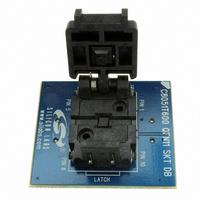
Manufacturer Part Number
C8051T600QDB
Description
BOARD SOCKET DAUGHTER QFN
Manufacturer
Silicon Laboratories Inc
Datasheet
1.C8051T600EDB.pdf
(188 pages)
Specifications of C8051T600QDB
Module/board Type
Socket Module - QFN
Data Bus Width
8 bit
Operating Supply Voltage
+ 1.8 V to + 3.6 V
Lead Free Status / RoHS Status
Contains lead / RoHS non-compliant
For Use With/related Products
C8051T600DK
Lead Free Status / Rohs Status
Lead free / RoHS Compliant
Other names
336-1406


C8051T600/1/2/3/4/5/6
26.3.1. Edge-triggered Capture Mode
In this mode, a valid transition on the CEXn pin causes the PCA to capture the value of the PCA coun-
ter/timer and load it into the corresponding module's 16-bit Capture/Compare register (PCA0CPLn and
PCA0CPHn). The CAPPn and CAPNn bits in the PCA0CPMn register are used to select the type of transi-
tion that triggers the capture: low-to-high transition (positive edge), high-to-low transition (negative edge),
or either transition (positive or negative edge). When a capture occurs, the Capture/Compare Flag (CCFn)
in PCA0CN is set to logic 1. An interrupt request is generated if the CCFn interrupt for that module is
enabled. The CCFn bit is not automatically cleared by hardware when the CPU vectors to the interrupt ser-
vice routine, and must be cleared by software. If both CAPPn and CAPNn bits are set to logic 1, then the
state of the Port pin associated with CEXn can be read directly to determine whether a rising-edge or fall-
ing-edge caused the capture.
Note: The CEXn input signal must remain high or low for at least two system clock cycles to be recognized by the
164
Port I/O
hardware.
Crossbar
Figure 26.4. PCA Capture Mode Diagram
CEXn
W
M
P
1
6
n
x
PCA0CPMn
C
O
M
E
n
x
C
A
P
P
n
Rev. 1.2
C
N
A
P
n
0
1
M
A
T
n
0 0 0 x
O
G
T
n
P
W
M
n
C
C
E
F
n
0
1
C
F
C
R
PCA0CN
PCA
Timebase
C
C
F
2
C
C
F
1
C
C
F
0
PCA Interrupt
Capture
PCA0CPLn
PCA0L
PCA0CPHn
PCA0H
Related parts for C8051T600QDB
Image
Part Number
Description
Manufacturer
Datasheet
Request
R

Part Number:
Description:
SMD/C°/SINGLE-ENDED OUTPUT SILICON OSCILLATOR
Manufacturer:
Silicon Laboratories Inc
Part Number:
Description:
Manufacturer:
Silicon Laboratories Inc
Datasheet:
Part Number:
Description:
N/A N/A/SI4010 AES KEYFOB DEMO WITH LCD RX
Manufacturer:
Silicon Laboratories Inc
Datasheet:
Part Number:
Description:
N/A N/A/SI4010 SIMPLIFIED KEY FOB DEMO WITH LED RX
Manufacturer:
Silicon Laboratories Inc
Datasheet:
Part Number:
Description:
N/A/-40 TO 85 OC/EZLINK MODULE; F930/4432 HIGH BAND (REV E/B1)
Manufacturer:
Silicon Laboratories Inc
Part Number:
Description:
EZLink Module; F930/4432 Low Band (rev e/B1)
Manufacturer:
Silicon Laboratories Inc
Part Number:
Description:
I°/4460 10 DBM RADIO TEST CARD 434 MHZ
Manufacturer:
Silicon Laboratories Inc
Part Number:
Description:
I°/4461 14 DBM RADIO TEST CARD 868 MHZ
Manufacturer:
Silicon Laboratories Inc
Part Number:
Description:
I°/4463 20 DBM RFSWITCH RADIO TEST CARD 460 MHZ
Manufacturer:
Silicon Laboratories Inc
Part Number:
Description:
I°/4463 20 DBM RADIO TEST CARD 868 MHZ
Manufacturer:
Silicon Laboratories Inc
Part Number:
Description:
I°/4463 27 DBM RADIO TEST CARD 868 MHZ
Manufacturer:
Silicon Laboratories Inc
Part Number:
Description:
I°/4463 SKYWORKS 30 DBM RADIO TEST CARD 915 MHZ
Manufacturer:
Silicon Laboratories Inc
Part Number:
Description:
N/A N/A/-40 TO 85 OC/4463 RFMD 30 DBM RADIO TEST CARD 915 MHZ
Manufacturer:
Silicon Laboratories Inc
Part Number:
Description:
I°/4463 20 DBM RADIO TEST CARD 169 MHZ
Manufacturer:
Silicon Laboratories Inc