AC164337 Microchip Technology, AC164337 Datasheet - Page 101
AC164337
Manufacturer Part Number
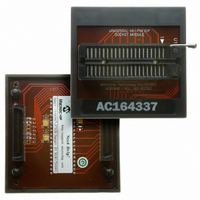
AC164337
Description
MODULE SOCKET FOR PM3 40DIP
Manufacturer
Microchip Technology
Datasheet
1.AC164335.pdf
(286 pages)
Specifications of AC164337
Module/board Type
Socket Module - DIP
Product
Microcontroller Accessories
Lead Free Status / RoHS Status
Not applicable / Not applicable
For Use With/related Products
MPLAB® PM3
Lead Free Status / RoHS Status
Lead free / RoHS Compliant, Not applicable / Not applicable


10.2
An input capture event will generate a device wake-up
or interrupt, if enabled, if the device is in CPU Idle or
Sleep mode.
Independent of the timer being enabled, the input
capture module will wake-up from the CPU Sleep or
Idle mode when a capture event occurs, if ICM<2:0> =
111 and the interrupt enable bit is asserted. The same
wake-up can generate an interrupt, if the conditions for
processing the interrupt have been satisfied. The
wake-up feature is useful as a method of adding extra
external pin interrupts.
10.2.1
CPU Sleep mode allows input capture module opera-
tion with reduced functionality. In the CPU Sleep
mode, the ICI<1:0> bits are not applicable, and the
input capture module can only function as an external
interrupt source.
The capture module must be configured for interrupt
only on the rising edge (ICM<2:0> = 111), in order for
the input capture module to be used while the device
is in Sleep mode. The prescale settings of 4:1 or 16:1
are not applicable in this mode.
© 2006 Microchip Technology Inc.
Input Capture Operation During
Sleep and Idle Modes
INPUT CAPTURE IN CPU SLEEP
MODE
Preliminary
10.2.2
CPU Idle mode allows input capture module operation
with full functionality. In the CPU Idle mode, the Inter-
rupt mode selected by the ICI<1:0> bits are applicable,
as well as the 4:1 and 16:1 capture prescale settings,
which are defined by control bits ICM<2:0>. This mode
requires the selected timer to be enabled. Moreover, the
ICSIDL bit must be asserted to a logic ‘0’.
If the input capture module is defined as ICM<2:0> =
111 in CPU Idle mode, the input capture pin will serve
only as an external interrupt pin.
10.3
The input capture channels have the ability to generate
an interrupt, based upon the selected number of cap-
ture events. The selection number is set by control bits
ICI<1:0> (ICxCON<6:5>).
Each channel provides an interrupt flag (ICxIF) bit. The
respective capture channel interrupt flag is located in
the corresponding IFSx STATUS register.
Enabling an interrupt is accomplished via the respec-
tive capture channel interrupt enable (ICxIE) bit. The
capture interrupt enable bit is located in the
corresponding IEC Control register.
dsPIC30F1010/202X
Input Capture Interrupts
INPUT CAPTURE IN CPU IDLE
MODE
DS70178C-page 99
Related parts for AC164337
Image
Part Number
Description
Manufacturer
Datasheet
Request
R

Part Number:
Description:
Manufacturer:
Microchip Technology Inc.
Datasheet:
Part Number:
Description:
Manufacturer:
Microchip Technology Inc.
Datasheet:
Part Number:
Description:
Manufacturer:
Microchip Technology Inc.
Datasheet:
Part Number:
Description:
Manufacturer:
Microchip Technology Inc.
Datasheet:
Part Number:
Description:
Manufacturer:
Microchip Technology Inc.
Datasheet:
Part Number:
Description:
Manufacturer:
Microchip Technology Inc.
Datasheet:
Part Number:
Description:
Manufacturer:
Microchip Technology Inc.
Datasheet:
Part Number:
Description:
Manufacturer:
Microchip Technology Inc.
Datasheet: