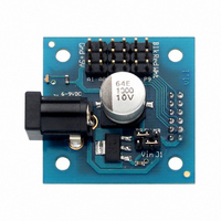
28301 Parallax Inc, 28301 Datasheet - Page 3

28301
Manufacturer Part Number
28301
Description
DAUGHTERBOARD 3PIN I/O MOBO
Manufacturer
Parallax Inc
Datasheet
1.28301.pdf
(8 pages)
Specifications of 28301
Accessory Type
Daughter Board, Power and I/O Interface
Product
Microcontroller Accessories
Lead Free Status / RoHS Status
Lead free / RoHS Compliant
For Use With/related Products
MoBoStamp, MoBoProp
Lead Free Status / RoHS Status
Lead free / RoHS Compliant
Available stocks
Company
Part Number
Manufacturer
Quantity
Price
for the correct jumper selection. This option is only available if the daughterboard is plugged into the
motherboard’s “A” socket. There is no Vin connection to the “B” socket.
The following diagram summarizes these connections:
Motherboard Connector
The motherboard connector can be used to plug the daughterboard into either the “A” or “B” socket on
the motherboard. When the daughterboard is not otherwise supported by card slots (e.g. in an
extrusion), you should use two of the threaded standoffs that came with the motherboard (with screws)
in the motherboard’s corner holes to secure the daughterboard in place.
External Device Interface Headers
This header block is configured as six 3-pin headers. Each header provides +5V, ground, and one signal
line to an external device. The legend on the daughterboard indicates which motherboard signals appear
at each connector, when the daughterboard is plugged into socket “A” . When it’s plugged into socket “B”,
these signals will be different. The following table summarizes these differences for the MoBoStamps:
Plugging this card into a MoBoProp motherboard will make these connections:
© Parallax, Inc. • PWR-I/O-DB (2006.09.13)
Important: When the Vin/J1 jumper is in place, never connect power to both the motherboard’s and
daughterboard’s external power connectors simultaneously. When the Vin is sourced from the
motherboard, always disconnect the Vin/J1 jumper.
Legend
Legend
A1
A0
A3
A2
P8
P9
A1
A0
A3
A2
P8
P9
External Power
+5V from
DB 5V MB
Vin J1
A1 (AVR I/O & analog input)
A0 (AVR I/O & analog input)
A3/P12 (AVR/BASIC Stamp I/O
& AVR PWM output)
A2/P11 (AVR/BASIC Stamp I/O
& AVR PWM output)
P8 (BASIC Stamp I/O w/ pull-up
& SDA)
P9 (BASIC Stamp I/O w/ pull-up
& SCL)
A1 (Propeller I/O)
A19 (Propeller analog input)
A0 (Propeller I/O)
A21 (Propeller analog input)
A3 (Propeller I/O)
A2 (Propeller I/O)
A5 (Propeller I/O w/ pull-up)
A4 (Propeller I/O w/ pull-up)
Socket “A” Signals
Socket “A” Signals
Motherboard
+5V from
DB 5V MB
Vin J1
Power Connector
Disable External
DB 5V MB
A9 (Propeller I/O)
A16 (Propeller analog input)
A8 (Propeller I/O)
A18 (Propeller analog input)
A11 (Propeller I/O)
A10 (Propeller I/O)
A13 (Propeller I/O w/ pull-up)
A12 (Propeller I/O w/ pull-up)
B1 (AVR I/O & analog input)
B0 (AVR I/O & analog input)
B3/P5 (AVR/BASIC Stamp I/O &
AVR PWM output)
B2/P7 (AVR/BASIC Stamp I/O &
AVR PWM output)
P0 (BASIC Stamp I/O w/ pull-up &
SDA)
P1 (BASIC Stamp I/O w/ pull-up &
SCL)
Vin J1
Socket “B” Signals
Socket “B” Signals
Power Connector
Enable External
DB 5V MB
Vin J1
Page 3 of 8


