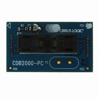
CDB2000-PC-CLK Cirrus Logic Inc, CDB2000-PC-CLK Datasheet - Page 10

CDB2000-PC-CLK
Manufacturer Part Number
CDB2000-PC-CLK
Description
BOARD EVAL GEN PURPOSE PLL DC
Manufacturer
Cirrus Logic Inc
Datasheet
1.CDB2000-PC-LCO.pdf
(26 pages)
Specifications of CDB2000-PC-CLK
Accessory Type
Daughter Card
Product
Audio Modules
Lead Free Status / RoHS Status
Contains lead / RoHS non-compliant
For Use With/related Products
CDB2000-MB
For Use With
598-1491 - BOARD EVAL GEN PURPOSE PLL
Lead Free Status / Rohs Status
Lead free / RoHS Compliant
Other names
598-1492
10
2.3.3
3. HARDWARE SYSTEM OVERVIEW
3.1
3.2
Power Supply
The entire CDK2000 platform is powered via the USB connector from a self-powered USB hub, which pro-
vides a voltage between 4.75 and 5.25 V. Other USB compliant power supplies, such as an AC (wall) adapt-
er or a DC (car) adapter, may be used as well. Whenever a suitable USB power supply is connected, D13
will be lit to indicate such.
A fixed voltage regulator (U10) provides the 3.3 V supply for the micro-controller, status LEDs, and three of
the four clock buffers.
An integrated Zetex™ boost converter, consisting of a controller (U9) and a rectifier (U8), generates an in-
termediate 7.2 V supply that feeds into an adjustable linear regulator (U5). The feedback network of the lin-
ear regulator is designed such that U5 generates either 3.3 V (with Q3 in the “on” state) or 6.5 V (with Q3
in the “off” state). This supply powers the DUT and the fourth clock buffer (U3). The selection between the
two output voltages is made via the VDUT.PROG.EN signal generated by the micro-controller. D4 is lit when
the higher (programming) voltage is applied to the DUT.
Furthermore, the adjustable linear regulator may be shut down in order to cut off the power supply to the
DUT when VDUT.EN is low (via inverter U4-C). Q2, in conjunction with R34, discharges the bulk decoupling
cap (C14) when the supply is powered down. The power-up/down state of U5 is controlled via the VDUT.EN
signal generated by the micro-controller. D3 indicates whether power is currently supplied to the DUT.
D11 indicates an error condition (overload) of the boost controller. In order to prevent damage to the boost
converter, the USB supply should be removed immediately when such an error occurs. Check the board
and connectors for shorts before proceeding.
Daughter Card Interface Headers
The CS2000 family device must be attached to the motherboard via one of the daughter cards described in
Section 1 on page
Make sure to align the large white triangle on the daughter card with the corresponding triangle on the moth-
erboard before inserting to ensure proper orientation.
Device Programming - Production Mode
12. To program the one-time-programmable memory in the CS2000 family device using the Wizard
13. To program the one-time-programmable memory in the CS2000 family device using the hardware
14. After the programming sequence is complete, the CS2000 family device will be powered down
15. Insert the next blank part into the socket.
16. Briefly press the push button S1 to power up the device
17. Repeat steps 13d
software, select “CDK Controls -> Initiate OTP Sequence...”.
controls on the CDB2000-MB
a) Close the Wizard software.
b) Verify that D9 is lit, indicating that the CS2000 family device is in hardware mode.
c) Place DIP switch position 5 into the lower (or closed) position to select production mode.
d) Press and hold the on-board push-button (S1) for more than 1 second to program the OTP
memory.
(indicated by D3 “VDUT” LED off) so that the device can be removed from the socket and the next
blank part can be inserted.
The following steps reference the CDB2000-MB hardware.
4. The desired daughter card plugs into the receptacles J1 and J8 on the motherboard.
-16
(of
Section
2.3.3) until the desired number of parts are programmed.
CDK2000
DS821DB1


