CDB2000-PC-LCO Cirrus Logic Inc, CDB2000-PC-LCO Datasheet - Page 16
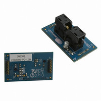
CDB2000-PC-LCO
Manufacturer Part Number
CDB2000-PC-LCO
Description
BOARD EVAL GEN PURPOSE PLL DC
Manufacturer
Cirrus Logic Inc
Datasheet
1.CDB2000-PC-LCO.pdf
(26 pages)
Specifications of CDB2000-PC-LCO
Accessory Type
Daughter Card
Product
Audio Modules
Lead Free Status / RoHS Status
Contains lead / RoHS non-compliant
For Use With/related Products
CDB2000-MB
For Use With
598-1491 - BOARD EVAL GEN PURPOSE PLL
Lead Free Status / Rohs Status
Lead free / RoHS Compliant
Other names
598-1493


16
5. USER INTERFACE ELEMENTS OVERVIEW
Table 4
position.
DIP switch
Designator
Reference
position
J1/J8
D10
D13
D11
J10
J11
D1
D2
D3
D4
D5
D6
D7
D8
D9
1
2
3
4
5
6
S1
S2
S3
Y1
J2
J3
J4
J5
J6
J7
J9
below serves as a quick reference to all user interface elements and
MICRO.MSEL
PROG.MSEL
BNC/OSC
PROG.SUCC
MODE CTRL
MICRO RST
PROG.RUN
PROG DUT
PROG.FAIL
MICRO.SW
Silkscreen
AUX_OUT
CLK_OUT
REF_CLK
CDB2000
Label
DUT.HW
DUT.SW
USB I/O
VPROG
CLK_IN
VDUT
M0
M1
M2
Label
IDUT
BNC
OSC
EOR
USB
C2
-
-
-
Programming sequence in progress (see
Programming sequence successful (see
Controls various board configuration aspects (see
M0 on DUT driven logic ‘low’
M1 on DUT driven logic ‘low’
M2 on DUT driven logic ‘low’
Programming sequence failed (see
REF_CLK input for CS2000, CS2100, and CS2200 sub-family devices
Boost converter overload -
Initiates various commands (see
Production mode active
CLK_IN input for CS2000, CS2100, and CS2300 sub-family devices
Switch down (closed)
On-board OSC active
Place shunt or measure voltage to determine DUT supply current
Table 4. User Interface Elements
Standard operation
Header for programming the micro-controller (factory use only)
Table 5. Dip Switch Positions
DUT is operating in software (control port or preview) mode
Input for external control signals (not supported)
DUT supply set to high (programming) voltage
Micro-controller is operating in software mode
Supports a DIP-8 or DIP-14 canned oscillator
REF_CLK source set to on-board oscillator
Board is connected to USB power supply
REF_CLK source set to BNC connector
Interface to CDB2000 (not supported)
DUT is operating in hardware mode
Daughter card receptacles
Reset micro-controller
DUT is powered up
AUX_OUT output
CLK_OUT output
unplug USB power supply immediately!
USB connector
Description
Section 4.1.3 on page 13
Section 4.4.3 on page 14
Section 4.4.3 on page 14
Section 4.4.3 on page 14
Table 5
M0 on DUT driven logic ‘high’
M1 on DUT driven logic ‘high’
M2 on DUT driven logic ‘high’
Reserved (factory use only)
Development mode active
Switch up (open)
outlines the various DIP switch
BNC input active
Table 5
below for details)
for details)
for details)
CDK2000
for details)
for details)
DS821DB1
Related parts for CDB2000-PC-LCO
Image
Part Number
Description
Manufacturer
Datasheet
Request
R

Part Number:
Description:
BOARD EVAL GEN PURPOSE PLL
Manufacturer:
Cirrus Logic Inc
Datasheet:

Part Number:
Description:
BOARD EVAL GEN PURPOSE PLL DC
Manufacturer:
Cirrus Logic Inc
Datasheet:

Part Number:
Description:
BOARD EVAL GEN PURPOSE PLL
Manufacturer:
Cirrus Logic Inc
Datasheet:
Part Number:
Description:
Development Kit
Manufacturer:
Cirrus Logic Inc
Datasheet:
Part Number:
Description:
Development Kit
Manufacturer:
Cirrus Logic Inc
Datasheet:


Part Number:
Description:
High-efficiency PFC + Fluorescent Lamp Driver Reference Design
Manufacturer:
Cirrus Logic Inc
Datasheet:
Part Number:
Description:
Development Kit
Manufacturer:
Cirrus Logic Inc
Datasheet:
Part Number:
Description:
Development Kit
Manufacturer:
Cirrus Logic Inc
Datasheet:

Part Number:
Description:
Development Kit
Manufacturer:
Cirrus Logic Inc
Datasheet:
Part Number:
Description:
Development Kit
Manufacturer:
Cirrus Logic Inc
Datasheet:
Part Number:
Description:
Development Kit
Manufacturer:
Cirrus Logic Inc
Datasheet:
Part Number:
Description:
Development Kit
Manufacturer:
Cirrus Logic Inc
Datasheet:

Part Number:
Description:
Ref Bd For Speakerbar MSA & DSP Products
Manufacturer:
Cirrus Logic Inc