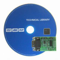
ATADAPCAN01 Atmel, ATADAPCAN01 Datasheet - Page 4

ATADAPCAN01
Manufacturer Part Number
ATADAPCAN01
Description
EXTENSION CAN ADD-ON TO STK500/1
Manufacturer
Atmel
Datasheet
1.ATADAPCAN01.pdf
(6 pages)
Specifications of ATADAPCAN01
Accessory Type
CAN Adapter
Product
Microcontroller Modules
Data Bus Width
8 bit
Core Processor
AT90CAN128
Interface Type
RS-232
Board Size
50 mm x 32 mm
For Use With/related Products
STK500, STK501
Lead Free Status / RoHS Status
Lead free / RoHS Compliant
Available stocks
Company
Part Number
Manufacturer
Quantity
Price
Company:
Part Number:
ATADAPCAN01
Manufacturer:
Atmel
Quantity:
135
Utilising CAN-
Transceiver Extra-
features
Slope Control (pin 8,
"CAN1" and "CAN2")
Standby Function (pin 8,
"CAN1" and "CAN2")
Shutdown Function
(pin 5, "CAN2")
Split Voltage (pin 5,
"CAN1")
4
AT90CAN128
Figure 2. Component Placement
Many CAN transceiver devices available have various extra functions accessible
through pins 5 and 8. The ATADAPCAN01 allows you to take advantage of some of
these features. Pin 8 on both "CAN1" and "CAN2" footprints are connected centre pin of
the "SLOPE CTRL" connector. Pin 5 of "CAN1" is connected to the centre-tap of the ter-
mination network, and pin 5 of "CAN2" is connected to R6 and C2 as shown in Figure 2.
CAN transceivers supporting slope or slew-rate control allow a resistor to be connected
between the RS pin (pin 8) and ground to limit the slope of the bus-driving signal. This
reduced EMI emmissions while restricting the maximum transmission rate. Pin 8 on both
"CAN1" and "CAN2" devices are connected to the centre pin of the "SLOPE CTRL"
jumper. Setting the jumper to the ON position, connects the centre pin to ground through
resistor R7, while setting it to the OFF position connects the centre pin directly to ground
(for no slope control, or high-speed mode). Refer to the CAN transceiver device docu-
mentation for information on selecting the value of R7 (24k by default).
On some CAN transceivers, pin 8 can be driven by a logic level to switch the transceiver
into standby mode. The centre pin of the "SLOPE CTRL" header (with the jumper
removed) can be connected to an I/O pin on the AVR device for this purpose. Your AVR
code should drive this signal as specified in the CAN transceiver documentation.
Some CAN transceivers have a SHUTDOWN function which is configured by an R-C
connection on pin 5. Pin 5 of the "CAN2" footprint is connected to resistor R6 to Vcc and
capacitor C2 to ground, as shown in the schematic diagram. By default R6 is a 0 ohm
connection to Vcc and C2 is not mounted. Both parts are 0603 size. Consult the CAN
transceiver documentation for further information.
The centre-point of the CAN bus termination (if enabled) can be stabilised by connecting
it to pin 5 of certain CAN transceivers. If the CAN transceiver supports this feature, a 0
ohm 0603 resistor can be mounted in R14, with the "SPLIT" and "TERM" jumpers set
accordingly (see Section ”CAN bus termination”).
4330B–CAN–03/04


