AC164110 Microchip Technology, AC164110 Datasheet - Page 12
AC164110
Manufacturer Part Number
AC164110
Description
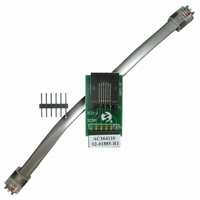
ADAPTER RJ-11 TO ICSP
Manufacturer
Microchip Technology
Datasheet
1.AC164110.pdf
(18 pages)
Specifications of AC164110
Accessory Type
Adapter
Convert From
RJ-11 Jack
Convert To
ICSP Header
Ic Cable Type
Program/Debug
Leaded Process Compatible
Yes
Rohs Compliant
Yes
Lead Free Status / RoHS Status
Lead free / RoHS Compliant
For Use With/related Products
ICD2
Lead Free Status / Rohs Status
Lead free / RoHS Compliant
For Use With
MPLAB REAL In-Circuit Emulator
Lead Free Status / RoHS Status
Lead free / RoHS Compliant, Lead free / RoHS Compliant


44-Pin Demo Board User’s Guide
1.4
1.5
DS41296A-page 8
44-PIN DEMO BOARD OVERVIEW
RUNNING THE DEFAULT DEMONSTRATION
The 44-Pin Demo Board is populated with a PIC16F917 MCU (U1), eight LEDs
(DS1-DS8), push button (SW1) and potentiometer (RP1). The board layout is shown in
Figure 1-1. The demo board has several test points to access the I/O pins of the MCU
and a surface mount prototyping area. The MCU can be programmed with the PICkit™
2 Microcontroller Programmer from header P1.
FIGURE 1-1:
The assembled 44-Pin Demo Board comes preprogrammed with a demonstration
program. To use this program, power the demo board (3.0 - 5.5V
Microcontroller Programmer, or a bench power supply connected to header P2. To use
the PICkit™ 2 Microcontroller Programmer, connect it to a PC USB port using the USB
cable. Start the PICkit™ 2 Microcontroller Programmer PC application and click on the
target power box to apply power to the demo board. The demo program will blink the
eight red lights in succession. Press the push button switch, labeled SW1, and the
sequence of the lights will reverse. Rotate the potentiometer, RP1, and the light
sequence will blink at a different rate.
Potentiometer RP1
44-PIN DEMO BOARD
PICkit™ 2 Programming Header
© 2006 Microchip Technology Inc.
DC
Push Button SW1
Surface Mount
LEDs DS1-DS8
) using a PICkit™ 2
Prototyping
Area
Related parts for AC164110
Image
Part Number
Description
Manufacturer
Datasheet
Request
R

Part Number:
Description:
Manufacturer:
Microchip Technology Inc.
Datasheet:
Part Number:
Description:
Manufacturer:
Microchip Technology Inc.
Datasheet:
Part Number:
Description:
Manufacturer:
Microchip Technology Inc.
Datasheet:
Part Number:
Description:
Manufacturer:
Microchip Technology Inc.
Datasheet:
Part Number:
Description:
Manufacturer:
Microchip Technology Inc.
Datasheet:
Part Number:
Description:
Manufacturer:
Microchip Technology Inc.
Datasheet:
Part Number:
Description:
Manufacturer:
Microchip Technology Inc.
Datasheet:
Part Number:
Description:
Manufacturer:
Microchip Technology Inc.
Datasheet: