TLRBP TDK Corporation, TLRBP Datasheet - Page 3
TLRBP
Manufacturer Part Number
TLRBP
Description
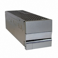
BLANKING PANEL
Manufacturer
TDK Corporation
Series
TLr
Specifications of TLRBP
Accessory Type
Blank Panel
For Use With
285-1646 - PWR SUP FNT END 48V 1000W 20A285-1645 - PWR SUP FNT END 24V 1000W 40A
Lead Free Status / RoHS Status
Lead free / RoHS Compliant
For Use With/related Products
TL Series
Lead Free Status / RoHS Status
Lead free / RoHS Compliant, Lead free / RoHS Compliant
Other names
285-1648


1 Safety and Recommended Practices
1.1 General practices
This product accepts a nominal AC voltage
between 100 and 240 VAC (±10%), 47 to
63 Hz, and produces a regulated output of
10.5-14VDC, 21-28 VDC, or 42-56 VDC
(depending upon deployed power modules)
capable of delivering a max of 300 Amperes
DC for 12 V power modules, max of 300
Amperes DC for 24 V power modules, or
max 250 Amperes DC for 48V power mod-
ules at an ambient operating temperature
range of -40oC to +75oC (depending upon
deployed power modules).
HAZARDOUS VOLTAGE AND ENERGY LEV-
ELS ARE PRESENT WHICH CAN PRODUCE
SERIOUS SHOCKS AND BURNS.
Only authorized, qualified, and trained per-
sonnel should attempt to work on this equip-
ment. Refer to datasheets for full product
specifications.
Observe all local and national electrical,
environmental, and workplace codes.
Each rack should be fed from a dedicated
AC branch circuit of a TN power system.
If a line cord(s) is(are) used as the AC con-
nection means, the plug end of the cord is
considered to be the primary disconnect
means, and reasonable access must be given
to the plug and receptacle area. The recep-
tacle must be fed with a breaker or fuse
according to Table 5 (12 V), Table 6 (24 V),
or Table 7 (48V).
For hard-wired AC connections, a readily
accessible disconnect device shall be incor-
porated in the building installation wiring.
Select a wall breaker and wire sizes accord-
ing to Table 5 (12V), Table 6 (24V), or Table
7 (48V).
3055 Del Sol Blvd • San Diego, CA 92154 • 1-800-LAMBDA-4
Suitable for mounting on concrete or other non-combustible surfaces
For use in restricted access locations only.
CAUTION: ALL POWER MODULES EMPLOY
INTERNAL DOUBLE POLE/NEUTRAL FUSING
Internal power module fuses are not field
accessible. They can be replaced only by
authorized factory service personnel.
WARNING: HIGH LEAKAGE CURRENT:
EARTH CONNECTION ESSENTIAL BEFORE
CONNECTING SUPPLY.
Use double hole, UL listed lugs for all DC
connections to prevent lug rotation and inad-
vertent contact with other circuits. Terminal
strip connections require only single hole
lugs.
Class 1, 90°C wire is recommended for all
DC connections. Minimum wire sizes are
shown in Table 9. In practice, loop voltage
drop considerations will usually dictate larger
than minimum safe wire size. Connections to
multiple loads are recommended to be made
through an external distribution with over-
current protection.
The alarm contacts are rated for a maximum
voltage of 60 V, SELV (Safety Extra Low
Voltage) and a maximum continuous current
of .5A.
Connection and mounting torque require-
ments are listed in Table 11.
Lambda does not recommend shipping the
rack with the power modules installed.
Power modules should be shipped in sepa-
rate boxes provided by Lambda.
TLR5-S S ERIES POWER SYSTEM
Revision 1 : January 2006
Page. 3
Related parts for TLRBP
Image
Part Number
Description
Manufacturer
Datasheet
Request
R

Part Number:
Description:
TDK DC to DC Converters, DC to AC Inverters
Manufacturer:
TDK Corporation
Datasheet:
Part Number:
Description:
TDK DC to DC Converters, DC to AC Inverters
Manufacturer:
TDK Corporation
Datasheet: