XG3 Excelsys Technologies Ltd, XG3 Datasheet - Page 3
XG3
Manufacturer Part Number
XG3
Description
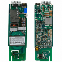
MODULE POWER 6VDC-15VDC 20A
Manufacturer
Excelsys Technologies Ltd
Series
powerModsr
Type
DC Output Module, Singler
Specifications of XG3
User Configuration
Configurator
Power (watts)
240W
Current
20A
Voltage - Output
12.0 nom, 6.0 ~ 15.0 range
Brand/series
Xlite Series
Configuration
Enclosed
Mounting Type
Panel
Number Of Outputs
1
Output
12 VDC @ 20 A
Power, Output
240 W
Primary Type
AC-DC
Special Features
Low Profile
Voltage, Input
85 to 264/120 to 380 VAC/VDC
Voltage, Output
12 VDC
For Use With
633-1031 - POWER CHASSIS 1340W 6 SLOT633-1030 - POWER CHASSIS 1340W 6 SLOT633-1029 - POWER CHASSIS 1200W 6 SLOT633-1028 - POWER CHASSIS 1000W 6 SLOT633-1027 - POWER CHASSIS 700W 6 SLOT633-1026 - POWER CHASSIS 400W 6 SLOT633-1025 - POWER CHASSIS 600W 4 SLOT633-1024 - POWER CHASSIS 400W 4 SLOT633-1023 - POWER CHASSIS 200W 4 SLOT633-1013 - POWER CHASSIS MED 1200W 6 SLOT633-1012 - POWER CHASSIS MED 1000W 6 SLOT633-1011 - POWER CHASSIS MED 700W 6 SLOT633-1010 - POWER CHASSIS MED 400W 6 SLOT633-1009 - POWER CHASSIS MED 600W 4 SLOT633-1008 - POWER CHASSIS MED 400W 4 SLOT633-1007 - POWER CHASSIS MED 200W 4 SLOT633-1006 - POWER CHASSIS 1200W 6 SLOT633-1005 - POWER CHASSIS 1000W 6 SLOT633-1004 - POWER CHASSIS 700W 6 SLOT633-1003 - POWER CHASSIS 400W 6 SLOT633-1002 - POWER CHASSIS 600W 4 SLOT633-1001 - POWER CHASSIS 400W 4 SLOT633-1000 - POWER CHASSIS 200W 4 SLOT
Lead Free Status / RoHS Status
Lead free / RoHS Compliant
Other names
633-1016


Xgen FLEXIBILITY
Voltage Adjustment - Local
The multi-turn potentiometer that adjusts each output within the specified
range may be accessed via the output panel of the power supply. Clockwise
rotation increases output voltage. Resolution is approximately 5% of nominal
voltage (Vnom) per turn.
Voltage Adjustment - Remote (resistive / electronic)
The output voltage may be adjusted or trimmed by means of an external
resistor or potentiometer network connected to the Vtrim pin. Linear Electronic
programming is also possible and may be implemented according to the
formula Vout = K Vcontrol. See Xgen series Designers’ Manual for full details.
Paralleling
To achieve increased current capacity, simply parallel outputs using the
standard parallel links. Excelsys ‘wireless’ sharing ensures that current
hogging is not possible.
Seriesing
To achieve increased output voltages, simply series outputs using standard
series links, paying attention to the requirements to maintain SELV levels if
required in your system.
Remote Sensing
When the load is remote from the power supply, the remote sense pins
may be used to compensate for drops in the power leads. Where the power
cabling contributes significant dynamic impedance, see Xgen series
Designers’ Manual.
Bias Voltage
A SELV isolated 5V (always on) bias voltage rated at 250mA is provided on
J2 to facilitate miscellaneous control functions.
Current Limit Adjustment
The output current limit setting may be adjusted (downwards only) by
means of an external resistor connection to the I trim pin.
Inhibit/Enable
Inhibiting may be implemented either globally or on a per module basis
(powerPac or powerMod inhibiting). Reverse logic (Enabling) may also be
implemented, see Xgen series Designers’ Manual.
Series
Standard parallel links
can be supplied. To
order, please use part
number XP1.
Standard serial links
can be supplied. To
order, please use part
number XS1.
Xgen SIGNALS
AC Fail
Open collector signal indicating that the input voltage has failed or is less than
80Vac. This signal changes state giving 5mS of warning before loss of output
regulation. See Xgen series Designers’ Manual for full specifications.
Temperature Alarm (Option 01)
Open collector signal indicating excessive powerPac temperatures due to fan
failure or operation beyond ratings. This signal is activated at least 10ms prior
to system shutdown.
Fan Fail (Option 01)
Open collector signal indicating that at least one of the system fans have
failed. This does not cause system shutdown.
Power Good
Opto-isolated output signal indicates that the powerMod is operating
correctly and output voltage is within normal band.
Opto transistor ON = Good.
Indication LEDs
Each powerMod has a visual indicator to identify that it is operating within
normal ratings. Very useful for system diagnosis.
Signal Connector Pinout
*Option 01 only
**See individual powerMod datasheets
Pin
1
2
3
4
5
6
7
8
J2
common
+5V bias
ac fail
fan fail*
global enable
temp alarm*
global inhibit
(powerPac)
J3
+sense
-sense
V trim
I trim
+inhibit/enable
-inhibit/enable
+power good
-power good
(powerMod TYPE A)
** J3
+pg (V2)
-pg (V2)
inhibit (V2)
common (V2)
+pg (V1)
-pg (V1)
inhibit (V1)
common (V1)
(powerMod Type B)
**
Related parts for XG3
Image
Part Number
Description
Manufacturer
Datasheet
Request
R

Part Number:
Description:
CONF MODULE POWER 6-15VDC 20A
Manufacturer:
Excelsys Technologies Ltd
Part Number:
Description:
EXCELSYS LED POWER SUPPLIES Brochure 2011
Manufacturer:
Excelsys Technologies Ltd
Part Number:
Description:
AC/DC Modular 12Vout & 42Vout (24A max) 1340W
Manufacturer:
Excelsys Technologies Ltd
Part Number:
Description:
AC/DC Modular 20Vout 1340W
Manufacturer:
Excelsys Technologies Ltd
Part Number:
Description:
AC/DC Modular 20Vout 1340W
Manufacturer:
Excelsys Technologies Ltd
Part Number:
Description:
AC/DC Modular 42Vout (24A max) & 12Vout 1340W
Manufacturer:
Excelsys Technologies Ltd
Part Number:
Description:
Ac/dc Modular Xgen PowerPac; Medical 4-slot Low Noise version 400W max
Manufacturer:
Excelsys Technologies Ltd
Part Number:
Description:
Ac/dc Modular Xgen PowerPac; Medical 6-slot Low Noise version 900W max
Manufacturer:
Excelsys Technologies Ltd

Part Number:
Description:
MODULE POWER 3.2VDC-6VDC 40A
Manufacturer:
Excelsys Technologies Ltd
Datasheet:

Part Number:
Description:
MODULE POWER 28VDC-58VDC 6A
Manufacturer:
Excelsys Technologies Ltd
Datasheet:

Part Number:
Description:
MODULE POWER 5VDC-28VDC 5A
Manufacturer:
Excelsys Technologies Ltd
Datasheet: