ZUP60-14/U TDK Corporation, ZUP60-14/U Datasheet - Page 51
ZUP60-14/U
Manufacturer Part Number
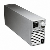
ZUP60-14/U
Description
PWR SUP BENCH PROG 0-60V 840W
Manufacturer
TDK Corporation
Series
ZUPr
Type
Programmabler
Specifications of ZUP60-14/U
Load Regulation
0.07%
Voltage - Output
0 ~ 60V
Number Of Outputs
1
Power (watts)
840W
Applications
Commercial
Power Supply Type
Switching (Closed Frame)
Voltage - Input
85 ~ 265VAC
Mounting Type
Chassis Mount
1st Output
0 ~ 60 VDC @ 14A
Size / Dimension
13.78" L x 5.51" W x 4.88" H (350mm x 140mm x 124mm)
Power (watts) - Rated
840W
Operating Temperature
0°C ~ 50°C
Efficiency
84%
Approvals
CE, EN, UL
Line Regulation
0.01%
Power Supply Output Type
Variable
No. Of Outputs
1
Output Voltage
60V
Output Current
14A
Power Rating
840W
Input Voltage
85V AC To 265V AC
Length
350mm
Width
140mm
Accuracy
0.02% + 35 mV
Brand/series
ZUP
Current, Output
14 A
Display Type
Digital Meter
Power, Output
840 W
Power, Rating
840 W (Max.)
Regulation, Line
0.01% + 5 mA⁄1 mV + 0.005%
Regulation, Load
0.07% + 7 mA⁄2 mV + 0.005%
Standards
UL Listed, CE Marked
Temperature Coefficient
30 ppm⁄°C (CV)⁄100 ppm⁄°C (CC)
Temperature, Operating, Maximum
50 °C
Temperature, Operating, Minimum
0 °C
Voltage, Input
85-265 VAC
Voltage, Noise
60 mV @ 20 MHz BW
Voltage, Output
60 VDC
Voltage, Ripple
5 mV @ 5 Hz to 1 MHz
Lead Free Status / RoHS Status
Lead free / RoHS Compliant
3rd Output
-
2nd Output
-
4th Output
-
Lead Free Status / Rohs Status
RoHS Compliant part
Other names
285-1679
ZUP6014/U
ZUP6014/U


5.5.3 Output control continued
5.5.4
5.5.4.1 Registers structure
1. Operational Status Register:
The operational status register records signals that are part of the power supply’s normal operation. In
addition to the normal operation data, the register holds an alarm bit which indicates that one of the
alarm (fault) register bits is set. The register is automatically updated and reading it does not change it’s
content. Clearing the register is done by DCL command. See table 5-5 for Operational Status Register
content.
Table 5-5: Operational status register content.
Note:
*1 In case of AC fail, the alarm status register ‘AC fail’ bit will be set but will not set the alarm bit.
alarm
13
cc/cv
fold
ast
out
srf
srv
srt
14
15
16
Bit Name
#
:UVPn;
Commands
:UVP?;
:ASTn;
:AST?;
Status control
Bit No
8
2
3
4
5
6
1
7
‘0’ - Indicates constant voltage, ‘1’ - constant current.
‘1’ - Indicates foldback protection is armed.
‘1’ - Indicates auto-restart is on, ‘0’ - auto-restart is off.
‘1’ - Indicates output is on , ‘0’ -output is off.
‘0’ - Indicates foldback protection SRQ is disabled , ‘1’ - enabled.
‘0’ - Indicates over voltage protection SRQ is disabled , ‘1’ - enabled.
‘0’ - Indicates over temp. protection SRQ is disabled , ‘1’ - enabled.
‘1’ - Indicates that an alarm register bit is set. (note*1)
Meaning
Sets the under-voltage protection limits in volts. Under-voltage range
settings are given in table 5-4:
Table 5-4: Under-voltage programming range.
Example - ZUP20-XY :UVP07.3;
example- UP07.3
Description
Returns the string
protection value. The under-voltage range is given in table 5-4.
Sets the auto-restart mode to On or Off.
:AST1; - Auto-restart is On
:AST0; - Auto-restart is Off
Returns the string
AS1 - Auto-restart is ON
AS0 - Auto-restart is Off
ZUP6-XY
ZUP10-XY
ZUP20-XY
ZUP36-XY
ZUP60-XY
ZUP80-XY
ZUP120-XY 000.0
Model
MIN.
0.00
0.00
00.0
00.0
00.0
00.0
AS
UP
MAX.
119.8
5.98
9.97
19.9
35.9
59.8
79.8
followed by the auto-restart mode status.
followed by the present programmed under-voltage
Related parts for ZUP60-14/U
Image
Part Number
Description
Manufacturer
Datasheet
Request
R

Part Number:
Description:
PWR SUP BENCH PROG 0-60V 420W
Manufacturer:
TDK Corporation
Datasheet:
Part Number:
Description:
PWR SUP BENCH PROG 0-6V 198W
Manufacturer:
TDK Corporation
Datasheet:
Part Number:
Description:
PWR SUP BENCH PROG 0-6V 396W
Manufacturer:
TDK Corporation
Datasheet:
Part Number:
Description:
PWR SUP BENCH PROG 0-6V 792W
Manufacturer:
TDK Corporation
Datasheet:

Part Number:
Description:
TDK DC to DC Converters, DC to AC Inverters
Manufacturer:
TDK Corporation
Datasheet:
Part Number:
Description:
TDK DC to DC Converters, DC to AC Inverters
Manufacturer:
TDK Corporation
Datasheet: