ZUP10-20/U TDK Corporation, ZUP10-20/U Datasheet - Page 31
ZUP10-20/U
Manufacturer Part Number
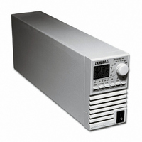
ZUP10-20/U
Description
PWR SUP BENCH PROG 0-10V 200W
Manufacturer
TDK Corporation
Series
ZUPr
Type
Enclosedr
Specifications of ZUP10-20/U
Number Of Outputs
1
Efficiency
77%
Voltage - Output
0 ~ 10V
Power (watts)
200W
Applications
Commercial
Power Supply Type
Switching (Closed Frame)
Voltage - Input
85 ~ 265VAC
Mounting Type
Chassis Mount
1st Output
0 ~ 10 VDC @ 20A
Size / Dimension
13.78" L x 4.88" W x 2.76" H (350mm x 124mm x 70mm)
Power (watts) - Rated
200W
Operating Temperature
0°C ~ 50°C
Approvals
CE, EN, UL
Line Regulation
0.01%
Load Regulation
0.01%
Output Current (max)
20A
Input Voltage
85 to 265V
Output Power (max)
200W
Input Frequency
47 to 63Hz
Screening Level
Commercial
Operating Temperature Min Deg. C
0C
Operating Temperature Max Deg. C
50C
Mounting Style
Desktop
Accuracy
0.02% + 8 mV
Brand/series
ZUP
Current, Output
20 A
Display Type
Digital Meter
Power, Output
200 W
Power, Rating
200 W (Max.)
Regulation, Line
0.01% + 2 mA⁄1 mV + 0.005%
Regulation, Load
0.01% + 5 mA⁄2 mV + 0.005%
Standards
UL Listed, CE Marked
Temperature Coefficient
30 ppm⁄°C (CV)⁄100 ppm⁄°C (CC)
Temperature, Operating, Maximum
50 °C
Temperature, Operating, Minimum
0 °C
Voltage, Input
85-265 VAC
Voltage, Noise
50 mV @ 20 MHz BW
Voltage, Output
10 VDC
Voltage, Ripple
5 mV @ 5 Hz to 1 MHz
Lead Free Status / RoHS Status
Lead free / RoHS Compliant
3rd Output
-
2nd Output
-
4th Output
-
Lead Free Status / Rohs Status
RoHS Compliant part
Other names
285-1668
Q1074270
ZUP10-20/U
ZUP1020/U
Q1074270
ZUP10-20/U
ZUP1020/U


4.2.3 Rear Panel Connections description
4.3.1 General
4.3.2 Prior to operation
4.3.3 Constant Voltage check
4.3
The following procedure ensures that the power supply is operational and may be used as a basic
incoming inspection check.
Check that the Rear panel external control receptacle is properly inserted into the connector and the
wires are connected as shown in Fig: 3-6. Connect the unit to an AC source as described in paragraph
3.6. Connect a DVM to the output terminals.
Turn-on the power supply. Turn on the output by pressing OUT pushbutton so the OUT LED illuminates.
Momentarily press V/A pushbutton, until the V LED illuminates and the VOLTS display shows FA_V.
The AMPS display will show the last setting of the output voltage. Rotate the Adjust knob at the front
panel and check that the output voltage can be varied throughout the entire range. Check that the
AMPS display shows the correct output voltage (within the display specifications). Momentarily press
V/A pushbutton again, so the A LED illuminates and the VOLTS display shows FA_A. The AMP display
will show the last setting of the output current. Rotate the Adjust knob and check that the AMP display
varies. Set the AMP display to the rated output current.
1
3
5
6
2
4
7
#
(6V to 60V models)
O u t p u t c o n n e c t o r
(80V and 120V models)
Remote Out
External control
Output Bus Bars
Ground thread
AC Inlet
Remote In
Connection
TURN-ON CHECKOUT PROCEDURE
Description
M4 thread for grounding either the positive or negative
output.
IEC type appliance inlet.
EIA/TIA-568A type connector, used for connecting power
supply to RS232 or RS485 port of computer for remote
control purposes. When using several power supply units
in a power system, the first unit Remote-in is connected to
the computer and the remaining units are chained,
Remote-In to Remote-Out.
EIA/TIA-568 type connector, used for chaining power
supplies to form a serial communication bus.
Connector containing control and signal lines for external
(remote) control of the power supply. +/- Sense, On/Off,
Output voltage and current programming by external
resistor and Output voltage and current programming by
external voltage and Output Good signal.
Bus bars for output connection. Use M6 or 1/4” screws for
load wire connections.
Male connector , PSC 1.5/3-M-PE , Phoenix.
3.6
5.3.4
5.3.4
3.8
3.7
Par.
Related parts for ZUP10-20/U
Image
Part Number
Description
Manufacturer
Datasheet
Request
R

Part Number:
Description:
PWR SUP BENCH PROG 0-10V 400W
Manufacturer:
TDK Corporation
Datasheet:
Part Number:
Description:
PWR SUP BENCH PROG 0-10V 800W
Manufacturer:
TDK Corporation
Datasheet:

Part Number:
Description:
TDK DC to DC Converters, DC to AC Inverters
Manufacturer:
TDK Corporation
Datasheet:
Part Number:
Description:
TDK DC to DC Converters, DC to AC Inverters
Manufacturer:
TDK Corporation
Datasheet: