DSP10-12 TDK Corporation, DSP10-12 Datasheet - Page 2
DSP10-12
Manufacturer Part Number
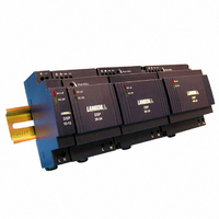
DSP10-12
Description
PWR SUP DIN RAIL 12V 10.0W .83A
Manufacturer
TDK Corporation
Series
DSPr
Specifications of DSP10-12
Power Supply Type
Switching (Closed Frame)
Voltage - Output
12V
Number Of Outputs
1
Power (watts)
10W
Applications
Commercial
Voltage - Input
90 ~ 264VAC
Mounting Type
DIN Rail
1st Output
12 VDC @ 830mA
Size / Dimension
2.19" L x 0.71" W x 3.58" H (55.6mm x 18mm x 90.9mm)
Power (watts) - Rated
10W
Operating Temperature
-25°C ~ 71°C
Efficiency
78%
Approvals
CE, EN, UL
Line Regulation
1%
Load Regulation
1%
Power Supply Output Type
Fixed
No. Of Outputs
1
Output Voltage
12V
Output Current
0.83A
Power Rating
10W
Input Voltage
90V AC To 264V AC / 120V DC To 370V DC
Brand/series
DSP Series
Configuration
Enclosed
Output
12 VDC @ 0.83 A
Power, Output
10 W
Primary Type
AC-DC
Special Features
PFC
Voltage, Input
90 to 264 VAC
Voltage, Output
12 VDC
Lead Free Status / RoHS Status
Lead free / RoHS Compliant
3rd Output
-
2nd Output
-
4th Output
-
Lead Free Status / Rohs Status
RoHS Compliant part
Other names
285-1225
DSP1012
DSP1012
Available stocks
Company
Part Number
Manufacturer
Quantity
Price
Company:

Part Number:
DSP10-12
Manufacturer:
TDK-LAMBDA
Quantity:
325


Read Instructions!
Disconnect system from supply network
Before start of operation
Ensure appropriate installation
In operation: No modifications!
Convection cooling
Warning: High voltage! Store energy!
Only connect/disconnect when the power
is off!
Before working with this unit, read these instructions
carefully and completely. Make sure that you have
understood all the information!
This unit complies with UL1310* for the requirements of NEC
Class 2 power only.
Before any installation, maintenance or modification work:
Disconnect your system from the supply network. Ensure that
it cannot be re-connected inadvertently!
Warning! Improper installation / operation impair safety and
result in operational difficulties or complete failure of the unit.
The unit must be installed and put into service appropriately
by qualified personnel. Compliance with the relevant
regulations must be ensured. Before operation is begun the
following conditions must be ensured, in particular:
As long as the unit is in operation: do not modify the
installation! The same applies also to the secondary side. Risk
of electric arcs and electric shock (fatal)!
Do not cover any ventilation holes!
Leave sufficient space around the unit for cooling!
The unit contains unprotected conductors carrying a lethal
high voltage, and components storing substantial amounts of
energy. Improper handling may result in an electric shock or
serious burn!
Connection to main power supply in compliance with
VDE01000 and EN50178.
With stranded wires: all strands must be secured in the
terminal blocks (potential danger of short circuit).
Unit and power supply cables must be properly fused; if
necessary a manually controlled disconnecting element must
be used to disengage from supply mains.
All output lines must be rated for the power supply output
current and must be connected with the correct polarity.
Sufficient air-cooling must be ensured.
Pollution Degree 2 environment.
The unit must not be opened except appropriately trained
personnel!
Do not introduce any object into the unit!
Keep away from fire and water!
Safety notes
(See Fig. 1)
* If the units are to be installed as Direct Plug-in Power Units and full compliance to UL1310 is required.
the units must be installed in an airtight distributor box that conforms to the requirements of UL1310.
Installation
Mounting
Snap on support rail
Technical Data
Permissible mounting position: keep ventilation holes clear,
leave space for cooling! Recommended to have 25mm
free space at all sides:
Input
Rated input Voltage
AC Voltage Range
DC Voltage Range
Frequency
Rated input Current (max)
Inrush Current (115Vac/230Vac)
Efficiency (Typ)
Output
Overvoltage protection
DC ON indicate(Green LED)
Ripple
Nominal Current
Rated over load protection
Current Limit
Holdup Time(230Vac)
General
Temperature
Derating (115/230 VAC)
Humidity
Case
MAX. Required free space
Dimensions
H x W x D inches (mm)
Weight
Approvals And Standard
UL / cUL
TUV
CE
Tilt the unit slightly rearwards.
Fit the unit over top hat rail.
Slide it downward until it hits the stop.
Press against the bottom front side for locking.
Shake the unit slightly to check the locking action.
Line regulation
Load regulation
Description
(See Fig. 1)
All specifications are typical at nominal line, full load,25 ; Unless otherwise specified.
(See Fig. 2)
UL508 Listed
UL1310
EN60950-1
EN61000-6-3, EN55022 Class B
EN61000-3-2, EN61000-3-3
EN61000-6-2, EN55024, EN61000-4-2, EN61000-4-3, EN61000-4-4
EN61000-4-5, EN61000-4-6, EN61000-4-8,EN61000-4-11
Listed
DSP10-05
1500 mA
>74%
>3V
Class 2 power, UL 60950-1 Recognized
Fold Forward (Currentrises, voltage drops to maintain constant power during overload )
Storage : -25 to + 85
Connection
Removal
DSP10-12
830 mA
Use only commercial cables designed for the indicated
voltage and current values!
With flexible cables: make sure that all stranded cable
are secured in the terminal.
Ensure proper polarity at output terminals!
>78%
Push the slider downwards (unlock). Gently lift
lower front edge of the unit (tipping) and remove.
>9V
o
C
2.5% /
100Vac ~ 240 Vac
25mm in all sides
3.58
90Vac ~ 264Vac
(91
< 15A / < 30A
20%~90% RH
from DIN Rail (See Fig. 4)
120-370 Vdc
110%~160%
Model No.
<50mVp-p
47-63Hz
> 30ms
300mA
120-145 %
<1.0 %
<1.0 %
Plastic
from 55
0.71
18
60g
(See Fig. 3)
, Operation : -25 to+ 71
55.6)
2.19
to 71
DSP10-15
670 mA
>78%
>11V
DSP10-24
420 mA
>80%
>20V
DM131-A3
Related parts for DSP10-12
Image
Part Number
Description
Manufacturer
Datasheet
Request
R

Part Number:
Description:
PWR SUP DIN RAIL 15V 10.1W .67A
Manufacturer:
TDK Corporation
Datasheet:

Part Number:
Description:
PWR SUP DIN RAIL 24V 10.1W .42A
Manufacturer:
TDK Corporation
Datasheet:
Part Number:
Description:
PWR SUP DIN RAIL 5V 7.5W 1.5A
Manufacturer:
TDK Corporation
Datasheet:

Part Number:
Description:
PWR SUP DIN RAIL 24V 1.25A 30W
Manufacturer:
TDK Corporation
Datasheet:
Part Number:
Description:
TDK DC to DC Converters, DC to AC Inverters
Manufacturer:
TDK Corporation
Datasheet:
Part Number:
Description:
TDK DC to DC Converters, DC to AC Inverters
Manufacturer:
TDK Corporation
Datasheet: