APXW005A0X3-SRZ Lineage Power, APXW005A0X3-SRZ Datasheet - Page 10
APXW005A0X3-SRZ
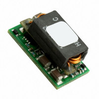
Manufacturer Part Number
APXW005A0X3-SRZ
Description
PWR MOD DC/DC NON-ISOL 9-36V 5A
Manufacturer
Lineage Power
Series
ProLynx™r
Type
Point of Load (POL) Non-Isolated with Remote On/Offr
Datasheet
1.APXW005A0X3-SRZ.pdf
(21 pages)
Specifications of APXW005A0X3-SRZ
Output
3 ~ 18V
Number Of Outputs
1
Power (watts)
90W
Mounting Type
Surface Mount
Voltage - Input
9 ~ 36V
Package / Case
7-SMD Module
1st Output
3 ~ 18 VDC @ 5A
Size / Dimension
0.80" L x 0.45" W x 0.34" H (20.3mm x 11.4mm x 8.5mm)
Operating Temperature
-40°C ~ 85°C
Efficiency
95.9%
Approvals
CSA, EN, UL, VDE
Input Voltage Range
9 V to 36 V
Output Voltage (channel 1)
3 VDC to 18 VDC
Output Current (channel 1)
2.5 A to 5 A
Package / Case Size
20.3 mm x 11.4 mm x 8.5 mm
Output Type
Non-Isolated
Output Voltage
3 VDC to 18 VDC
Product
Non-Isolated / POL
Lead Free Status / RoHS Status
Lead free / RoHS Compliant
3rd Output
-
2nd Output
-
Lead Free Status / Rohs Status
Lead free / RoHS Compliant
Other names
555-1172-2
CC109151916
CC109151916
Available stocks
Company
Part Number
Manufacturer
Quantity
Price
Company:

Part Number:
APXW005A0X3-SRZ
Manufacturer:
GENERGY
Quantity:
120
Part Number:
APXW005A0X3-SRZ
Manufacturer:
GEENER
Quantity:
20 000


Test Configurations
Figure 25. Input Reflected Ripple Current Test
Setup.
Figure 26. Output Ripple and Noise Test Setup.
Figure 27. Output Voltage and Efficiency Test Setup.
Preliminary Data Sheet
October 28, 2010
NOTE: All voltage measurements to be taken at the module
LINEAGE
TO OSCILLOSCOPE
NOTE: Measure input reflected ripple current with a simulated
COM
Efficiency
Vo+
R
R
terminals, as shown above. If sockets are used then
Kelvin connections are required at the module terminals
to avoid measurement errors due to socket contact
resistance.
NOTE: All voltage measurements to be taken at the module
distribution
distribution
source inductance (L
possible battery impedance. Measure current as shown
above.
POWER
terminals, as shown above. If sockets are used then
Kelvin connections are required at the module terminals
to avoid measurement errors due to socket contact
resistance.
R
R
contact
contact
η =
@ 20°C 100kHz
COPPER STRIP
E.S.R.<0.1Ω
0.1uF
C
Electrolytic
S
1000μF
L
1μH
TEST
V
IN
V
V
V
COM
TEST
IN
O
IN
(+)
GROUND PLANE
. I
. I
) of 1μH. Capacitor C
O
IN
10uF
COM
V
O
Tantalum
2x100μF
V
C
x 100 %
O
IN
9 – 36Vdc input; 3Vdc to 18Vdc output; 5A to 2.5A output current
CURRENT PROBE
SCOPE USING
BNC SOCKET
R
R
contact
contact
S
offsets
V
COM
IN
(+)
R
R
RESISTIVE
LOAD
9-36V ProLynx
distribution
distribution
R
LOAD
Design Considerations
Input Filtering
The 9-36V ProLynx
a low ac-impedance source. A highly inductive
source can affect the stability of the module. An input
capacitance must be placed directly adjacent to the
input pin of the module, to minimize input ripple
voltage and ensure module stability.
To minimize input voltage ripple, ceramic capacitors
are recommended at the input of the module. Figure
28 shows the input ripple voltage for various output
voltages at maximum load current with 2x10 µF or
3x10 µF ceramic capacitors and an input of 12V,
while Fig. 29 shows the input ripple for an input
voltage of 28V.
Figure 28. Input ripple voltage for various output
voltages with 2x10 µF or 3x10 µF ceramic
capacitors at the input (maximum load). Input
voltage is 12V.
Figure 29. Input ripple voltage for various output
voltages with 2x10 µF or 3x10 µF ceramic
capacitors at the input (maximum load). Input
voltage is 28V.
TM
250
225
200
175
150
125
100
275
250
225
200
175
150
125
100
5A: Non-isolated DC-DC Power Modules
3
3
5
TM
4
Output Voltage (Vdc)
Output Voltage (Vdc)
7
module should be connected to
9
5
2x10uF
3x10uF
11
2x10uF
3x10uF
6
13
15
7
17
8
10
Related parts for APXW005A0X3-SRZ
Image
Part Number
Description
Manufacturer
Datasheet
Request
R

Part Number:
Description:
Manufacturer:
Lineage Power
Datasheet: