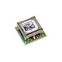
APTH003A0X4-SRZ Lineage Power, APTH003A0X4-SRZ Datasheet - Page 16

APTH003A0X4-SRZ
Manufacturer Part Number
APTH003A0X4-SRZ
Description
DC-DC 0.6-3.63V @ 3A
Manufacturer
Lineage Power
Series
Pico TLynx™r
Type
Point of Load (POL) Non-Isolated with Remote On/Offr
Datasheet
1.APTH003A0X-SRZ.pdf
(24 pages)
Specifications of APTH003A0X4-SRZ
Output
0.6 ~ 3.63V
Number Of Outputs
1
Power (watts)
10W
Mounting Type
Surface Mount
Voltage - Input
2.4 ~ 5.5V
Package / Case
10-SMD Module
1st Output
0.6 ~ 3.63 VDC @ 3A
Size / Dimension
0.48" L x 0.48" W x 0.25" H (12.2mm x 12.2mm x 6.3mm)
Power (watts) - Rated
10W
Operating Temperature
-40°C ~ 85°C
Efficiency
94%
Approvals
CSA, EN, UL, VDE
Product
Non-Isolated / POL
Output Power
11 W
Input Voltage Range
2.4 V to 5.5 V
Output Voltage (channel 1)
0.6 V to 3.63 V
Output Current (channel 1)
3 A
Output Type
Non-Isolated
Output Voltage
0.6 V to 3.63 V
Lead Free Status / RoHS Status
Lead free / RoHS Compliant
3rd Output
-
2nd Output
-
Lead Free Status / Rohs Status
Details
Data Sheet
April 7, 2011
Recommended values of R
output capacitor combinations are given in Tables 2, 3,
4 and 5. Tables 2 and 4 show the recommended
values of R
ceramic output capacitors up to 470uF that might be
needed for an application to meet output ripple and
noise requirements for 5Vin and 3.3Vin respectively.
Selecting R
ensure stable operation of the module.
In applications with tight output voltage limits in the
presence of dynamic current loading, additional output
capacitance will be required. Tables 3 and 5 list
recommended values of R
meet 2% output voltage deviation limits for some
common output voltages in the presence of a 1.5A to
3A step change (50% of full load), with an input
voltage of 5Vin and 3.3Vin respectively
Please contact your Lineage Power technical
representative to obtain more details of this feature as
well as for guidelines on how to select the right value
of external R-C to tune the module for best transient
performance and stable operation for other output
capacitance values or input voltages other than 3.3 or
5V.
Table 2. General recommended values of of R
and C
capacitor combinations.
Table 3. Recommended values of R
to obtain transient deviation of ≤2% of Vout for a
1.5A step load with Vin=5V.
Table 4. General recommended values of of R
and C
ceramic capacitor combinations.
LINEAGE
R
C
Vo
Co
ΔV
TUNE
TUNE
R
C
R
C
Co
Co
TUNE
TUNE
TUNE
TUNE
TUNE
TUNE
6800pF
59mV
1x47μF 2x47μF 4x47μF 6x47μF 10x47μF
1x47μF 2x47μF 4x47μF 6x47μF 10x47μF
6800pF
47μF
3.3V
POWER
for Vin=5V and various external ceramic
for Vin=3.3V and various external
TUNE
1 x
TUNE
33
15nF
33
33
and C
and C
35mV
47μF
15nF
15nF
2.5V
27nF
2 x
33
33
33
TUNE
TUNE
for different values of
TUNE
according to Table 2 will
TUNE
35mV
33nF
47nF
47μF
15nF
1.8V
33
2 x
33
33
and C
and C
2.4 – 5.5Vdc input; 0.6Vdc to 3.63Vdc output; 3A output current
47nF
56nF
21mV
47μF
33nF
1.2V
33
33
TUNE
TUNE
TUNE
4 x
33
in order to
for different
and C
2 x 47μF
56nF
68nF
Polymer
+330μF
12mV
33
33
Pico TLynx
82nF
0.6V
33
TUNE
TUNE
TUNE
TM
Table 5. Recommended values of R
to obtain transient deviation of ≤2% of Vout for a
1.5A step load with Vin=3.3V.
3A: Non-isolated DC-DC Power Modules
R
C
Vo
Co
ΔV
TUNE
TUNE
2 x 47μF 2 x 47μF 4 x 47μF
46mV
22nF
2.5V
33
32mV
27nF
1.8V
33
24mV
47nF
1.2V
33
TUNE
4 x 47μF
Polymer
+330μF
150nF
12mV
0.6V
33
and C
TUNE
16


