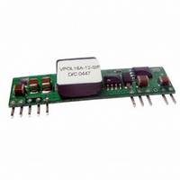
VPOL16A-12-SIP CUI Inc, VPOL16A-12-SIP Datasheet

VPOL16A-12-SIP
Specifications of VPOL16A-12-SIP
Related parts for VPOL16A-12-SIP
VPOL16A-12-SIP Summary of contents
Page 1
... Power De-Rating Curves 7.5 Efficiency vs Load Curves 7.6 Input Capacitance at the Power Module 7.7 Test Set-Up 7.8 Remote Sense Compensation 7.8 VPOL16A-12-SIP Series Output Voltage Adustment. 7.9 Output Ripple and Noise Measurement 7.10 Output Capacitance 7.11 VPOL16A-12-SIP Reflow Profile 8. MECHANICAL OUTLINE DIAGRAMS 8 ...
Page 2
... Monotonic Startup with pre-bias at the output. UL/IEC/EN60950 Certified. 3. General Description 3.1 Electrical Description A block diagram of the VPOL16A-12-SIP Series converter is shown in Figure 1. Extremely high efficiency power conversion is achieved through the use of synchronous rectification and drive techniques. Essentially, the powerful VPOL16A-12-SIP series topology is based on a non-isolated synchronous buck converter ...
Page 3
... PART NUMBER: VPOL16A-12-SIP 4. Technical Specifications (All specifications are typical at nominal input, full load at 25°C unless otherwise noted.) PARAMETER ABSOLUTE MAXIMUM RATINGS Input Voltage Continuous Operating Temp erature See Thermal Considerations Section Storage Temperature INPUT CHARACTERISTICS Operating Input Voltage Input Under-Voltage Lockout ...
Page 4
... PART NUMBER: VPOL16A-12-SIP PARAMETER DYNAMIC CHARACTERISTICS Output Voltage Transient Response Error Brand Setting Time (within 1% Vout nominal) EFFICIENCY 100% Load ISOLATION CHARACTERISTICS Input to Output FEATURE CHARACTERISTICS Switching Frequency ON/OFF Control, Positive Logic Remote On/Off Logic Low (Module Off) Logic High (Module On) ...
Page 5
... Layout Design Challenges. In optimizing thermal design the PCB is utilized as a heat sink. Also some heat is transferred from the VPOL16A-12-SIP module to the main board through connecting pins. The system designer or the end user must ensure that other components and metal in the vicinity of the ...
Page 6
... Figure 6. Figures 8 & 9 represent the test data. Note that the airflow is parallel to the long axis of the module as shown in Fig 6 for the VPOL16A-12-SIP. The temperature at either location should not exceed 120 °C. The output power of the module should not exceed the rated power for the module (VO, set x IO, max) ...
Page 7
... PART NUMBER: VPOL16A-12-SIP TYPICAL POWER DERATING FOR 5 Vin 3.3 Vout 0LFM 8 100LFM 6 200LFM 300LFM Ambient Temperature( C) NOTE: 1. specific input & output derating curves available, please contact V-Infinity for detail th 20050 SW 112 Ave. Tualatin, Oregon 97062 DESCRIPTION: point of load converter 100 o phone 503.612.2300 fax phone rev ...
Page 8
... PART NUMBER: VPOL16A-12-SIP 7.5 Efficiency vs Load Curves (Fig. 9) VPOL16A-12-SIP Vo=5.0V (Eff Vs Io) 100% 95% 90% 85% 80% 75% 70 Current Load (A) VPOL16A-12-SIP Vo=2.5V (Eff Vs Io) 100% 95% 90% 85% 80% 75% 70 Current Load (A) th 20050 SW 112 Ave. Tualatin, Oregon 97062 DESCRIPTION: point of load converter 100% 95% ...
Page 9
... PART NUMBER: VPOL16A-12-SIP VPOL16A-12-SIP Vo=1.8V (Eff Vs Io) 100% 95% 90% 85% 80% 75% 70% 65% 60 Current Load (A) VPOL16A-12-SIP Vo=1.2V (Eff Vs Io) 100% 95% 90% 85% 80% 75% 70% 65% 60 Current Load (A) th 20050 SW 112 Ave. Tualatin, Oregon 97062 DESCRIPTION: point of load converter 100% 95% 90% 85% 80% 75% 9.0V 12V ...
Page 10
... PART NUMBER: VPOL16A-12-SIP 7.6 Input Capacitance at the Power Module The VPOL16A-12-SIP converters must be connected to a low AC source impedance. To avoid probl ems with loop stability source inductance should be low. Also, the input capacitors should be placed close to the converter input pins to de-couple distribution inductance. ...
Page 11
... VPOL16A-12-SIP Reflow Profile _ 1000 ) An example of the VPOL16A-12-SIP reflow profile is given in Figure 15. 75 Equipment used: SMD HOT AIR REFLOW HD-350SAR Alloy: AMQ-M293TA or N C-SMQ92 IND-82088 SN63 Rtrim (Kohm) phone 503.612.2300 fax ...
Page 12
... Tolerance: x.xx ±0.02 in. (0.5mm) , x.xxx ±0.010 in. (0.25 mm) unless otherwise noted SIZE VPOL16A-12-SIP 2.00(50. 0.14(3.6) 0.010(0.25) min. 0.025(0.64) 0.100(2.54) 1.000(25.40) 0.400(10.20) Figure 19 VPOL16A-12-SIP Mechanical Outline Diagram th 20050 SW 112 Ave. Tualatin, Oregon 97062 DESCRIPTION: point of load converter 0.327(8.30)max. 0.23(5. 0.512(13.00) 0.28(7.1) 0.050(1.30) 0.025(0.64) phone 503 ...


