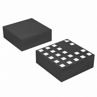
LTM8020MPV#PBF Linear Technology, LTM8020MPV#PBF Datasheet - Page 5

LTM8020MPV#PBF
Manufacturer Part Number
LTM8020MPV#PBF
Description
IC DC/DC UMODULE 200MA 21-LGA
Manufacturer
Linear Technology
Series
µModuler
Type
Point of Load (POL) Non-Isolatedr
Datasheet
1.LTM8020EVPBF.pdf
(16 pages)
Specifications of LTM8020MPV#PBF
Output
1.25 ~ 5 V
Number Of Outputs
1
Power (watts)
1W
Mounting Type
Surface Mount
Voltage - Input
4 ~ 36 V
Package / Case
21-LGA
1st Output
1.25 ~ 5 VDC @ 200mA
Size / Dimension
0.25" L x 0.25" W x 0.09" H (6.25mm x 6.25mm x 2.32mm)
Power (watts) - Rated
1W
Operating Temperature
-55°C ~ 125°C
Lead Free Status / RoHS Status
Lead free / RoHS Compliant
3rd Output
-
2nd Output
-
Available stocks
Company
Part Number
Manufacturer
Quantity
Price
PIN FUNCTIONS
TYPICAL PERFORMANCE CHARACTERISTICS
V
LTM8020’s internal regulator and to the internal power
switch. These pins must be locally bypassed with an
external, low ESR capacitor of at least 1μF .
V
An external capacitor is connected from V
most applications. Apply output load between these pins
and GND.
BIAS (Pin C3): The BIAS pin connects to the internal
boost Schottky diode and to the internal regulator. Tie to
V
than 3V otherwise. When BIAS > 3V the internal circuitry
will be powered from this pin to improve efficiency. Main
regulator power will still come from V
IN
OUT
OUT
25
20
15
10
5
0
(Pins A1, A2): The V
0
Temperature Rise vs Input
Voltage (Full Load, T
(Pins A4, A5, B4, B5, C4, C5): Power Output Pins.
when V
10
OUT
INPUT VOLTAGE (V)
20
> 3V or to another DC voltage greater
5V
OUT
3.3V
30
A
OUT
= 25°C)
IN
40
pins supply current to the
8020 G13
50
INPUT CURRENT
IN
.
100mA/DIV
OUT
2V/DIV
5V/DIV
SHDN
V
OUT
to GND in
Turn-On Behavior
(6V
IN
, 3.3V
OUT
, No Load)
50μs/DIV
SHDN (Pin C1): The SHDN pin is used to put the LTM8020 in
shutdown mode. Tie to ground to shut down the LTM8020.
Apply 2V or more for normal operation. If the shutdown
feature is not used, tie this pin to V
GND (Pins C2, D1, D2, D3, D4, D5, E2, E3, E4, E5): The
GND connections serve as the main signal return and the
primary heat sink for the LTM8020. Tie the GND pins to
a local ground plane below the LTM8020 and the circuit
components. Return the feedback divider to this signal.
ADJ (Pin E1): The LTM8020 regulates its ADJ pin to 1.25V.
Connect the adjust resistor from this pin to GND. The
value of this adjust resistor is determined by the equation
R
that the ADJ pin is open circuit if V
ADJ
= 623.75/(V
T
A
= 25°C unless otherwise noted.
8020 G14
OUT
– 1.25), where R
–10
90
80
70
60
50
40
30
20
10
0
0
Radiated Emissions
36V
5V
FULL LOAD
OUT
IN
200
FREQUENCY (MHz)
OUT
IN
400
.
ADJ
LTM8020
= 1.25V.
600
is in kΩ. Note
CLASS B LIMIT
EN55022
800
8020 G15
8020fd
5
1000


