VPOL5A-5-SIP CUI Inc, VPOL5A-5-SIP Datasheet - Page 6
VPOL5A-5-SIP
Manufacturer Part Number
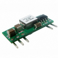
VPOL5A-5-SIP
Description
CONVERTER DC/DC 3.63V OUT 5A SIP
Manufacturer
CUI Inc
Series
V-Infinity VPOL5Ar
Type
Point of Load (POL) Non-Isolatedr
Datasheet
1.VPOL5A-5-SIP.pdf
(10 pages)
Specifications of VPOL5A-5-SIP
Output
0.75 ~ 3.63V
Number Of Outputs
1
Power (watts)
18W
Mounting Type
Through Hole
Voltage - Input
3 ~ 5.5V
Package / Case
5-SIP Module
1st Output
0.75 ~ 3.63 VDC @ 5A
Size / Dimension
0.90" L x 0.22" W x 0.40" H (22.9mm x 5.6mm x 10.2mm)
Power (watts) - Rated
18W
Operating Temperature
-40°C ~ 85°C
Efficiency
94%
Approvals
EN, IEC, UL
Lead Free Status / RoHS Status
Lead free / RoHS Compliant
3rd Output
-
2nd Output
-
Other names
102-1287


PART NUMBER: VPOL5A-5-SIP
0.20(5.1)
6. Safety
6.1 Input Fusing and Safety Considerations.
Agency Approvals: The power supply shall be submitted to and
receive formal approval from the following test agencies.
1.The power supply shall be approved by a nationally recognized
testing laboratory to UL/CSA 60950 3
EN60950 (International)
2. CB Certificate from an internationally recognized test house in
accordance with EN 60950.
The VPOL5A-5-SIP series converters do not have an internal fuse.
However, to achieve maximum safety and system protection, always
use an input line fuse. The safety agencies require a time-delay fuse
with a maximum rating of 10 A.
7. Applications
7.1 Layout Design Challenges.
In optimizing thermal design the PCB is utilized as a heat sink. Also
some heat is transferred from the SIP module to the main board
through connecting pins. The system designer or the end user must
ensure that other components and metal in the vicinity of the
VPOL5A-5-SIP series meet the spacing requirements to which the
system is approved.
Low resistance and low inductance PCB layout traces are the norm
and should be used where possible. Due consideration must also be
given to proper low impedance tracks between power module, input
and output grounds. The recommended SIP footprint as shown in
figure 5.
7.2 Convection Requirements for Cooling
To predict the ap proximate cooling needed for the module, refer to the
Power De-rating curves in Figures 10 to 13. These derating curves are
approximations of the ambient temperatures and airflows required to
keep the power module temperature below its maximum rating. Once
the module is assembled in the actual system, the module’s
temperature should be checked as shown in Figure 6 to ensure it does
not exceed 110°C.
Proper cooling can be verified by measuring the power module’s
temperature at Q1-pin 6 as shown in Figure 6.
20050 SW 112
LAYOUT PA TTERN
TOP VIEW
Figure 5. Recommended SIP Footprint
th
Ave. Tualatin, Oregon 97062
0.24(6.1)
rd
Edition (North America) and
1.1mm PLATED THROUGH HOLE
1.6mm PAD SIZE
All Dimmension In Inches(mm)
Tolerance :
.XX=
.XXX=
±0
±0
.02 (
.010 (
±
0. 5 )
±
phone
phone 503.612.2300 fax
0.25 )
DESCRIPTION: point of load converter
Note that airflow is parallel to the long axis of the module as shown in Fig7.
7.3 Thermal Considerations
The power module operates in a variety of thermal environments;
however, sufficient cooling should be provided to help ensure reliable
operation of the unit. Heat is removed by conduction, convection, and
radiation to the surrounding environment. The thermal data presented
is based on measurements taken in a set-up as shown in Figure7.
Figures 8 and 9 represent the test data. Note that the airflow is parallel
to the long axis of the module as shown in Figure7 for the VPOL5A-5-SIP.
The temperature at either location should not exceed 110 °C. The
output power of the module should not exceed the rated power for the
module (VO, set x IO, max). The test setup shown in Figure 7 and EUT
need to solder on 33mm x 40.38mm(1.300'' x 1.59'') test pcb.
Bakelite
Tunnel
W ind
Figure 7. Temperature Measurement Location for SIP
Note : Dimensions are in millimeters and (inches)
Figure 6. Thermal Test Setup
fax 503.612.2382
25.4(1.0)
12.7(0.5)
Air
flow
76.2(3.0)
Power Module
ambient temperature
and airflow
Thermocuple Location
for measuring
rev.
page
date
08/2007
6 of 10
Related parts for VPOL5A-5-SIP
Image
Part Number
Description
Manufacturer
Datasheet
Request
R

Part Number:
Description:
CONVERTER DC/DC 3.63V OUT 5A SMD
Manufacturer:
CUI Inc
Datasheet:

Part Number:
Description:
CONVERTER DC/DC 5.0V OUT 5A SMD
Manufacturer:
CUI Inc
Datasheet:

Part Number:
Description:
CONVERTER DC/DC 5.0V OUT 5A SIP
Manufacturer:
CUI Inc
Datasheet:

Part Number:
Description:
CABLE ASSY LATCH 5PIN 5X22AWG 1'
Manufacturer:
CUI Inc
Datasheet:

Part Number:
Description:
CABLE ASSY LATCH 5PIN 5X22AWG 1'
Manufacturer:
CUI Inc
Datasheet:

Part Number:
Description:
CABLE SHLD LATCH 5PIN 24AWG 6'
Manufacturer:
CUI Inc
Datasheet:

Part Number:
Description:
LINE DRIVER CABLE FOR AMT-102 1M
Manufacturer:
CUI Inc
Datasheet:

Part Number:
Description:
LINE DRIVER CABLE FOR AMT-103 1M
Manufacturer:
CUI Inc
Datasheet:

Part Number:
Description:
CABLE SHLD MATING 5PIN 24AWG 6'
Manufacturer:
CUI Inc
Datasheet:

Part Number:
Description:
CABLE ASSY LATCH 5PIN 5X24AWG 6'
Manufacturer:
CUI Inc
Datasheet:

Part Number:
Description:
SPEAKER ALNICO 8OHM 2W 100MM SQR
Manufacturer:
CUI Inc
Datasheet:

Part Number:
Description:
ac-dc converter
Manufacturer:
CUI [CUI INC]
Datasheet:
Part Number:
Description:
MEDICAL SWITCHING POWER SUPPLY
Manufacturer:
CUI [CUI INC]
Datasheet:
Part Number:
Description:
DC-DC Converter
Manufacturer:
CUI [CUI INC]
Datasheet:
Part Number:
Description:
DC/DC Converter
Manufacturer:
CUI [CUI INC]
Datasheet: