R-743.3P Recom Power Inc, R-743.3P Datasheet - Page 2
R-743.3P
Manufacturer Part Number
R-743.3P
Description
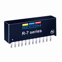
CONV DC/DC 4A 3.3V OUT VERT SIP
Manufacturer
Recom Power Inc
Series
Innoline R-7xxxr
Type
Point of Load (POL) Non-Isolated with Remote On/Offr
Datasheet
1.R-743.3P.pdf
(4 pages)
Specifications of R-743.3P
Output
3.3V
Number Of Outputs
1
Power (watts)
13W
Mounting Type
Through Hole
Voltage - Input
4.5 ~ 28V
Package / Case
12-SIP Module
1st Output
3.3 VDC @ 4A
Size / Dimension
1.27" L x 0.36" W x 0.59" H (32.2mm x 9.1mm x 15mm)
Power (watts) - Rated
13.2W
Operating Temperature
-40°C ~ 85°C
Efficiency
93%
Approvals
EN, UL
Input Voltage Range
4.5 V to 28 V
Output Voltage (channel 1)
3.3 V
Output Current (channel 1)
4 A
Package / Case Size
32.2 mm x 9.1 mm x 15 mm
Output Voltage
3.3 V
Lead Free Status / RoHS Status
Lead free / RoHS Compliant
Other names
80099127
945-1027
945-1027
Available stocks
Company
Part Number
Manufacturer
Quantity
Price
Company:

Part Number:
R-743.3P
Manufacturer:
Recom Power Inc
Quantity:
135


I-42
INNOLINE
DC/DC-Converter
Characteristics
Output Voltage Range
Output Current
Output Current Limit
Short Circuit Input Current
Short Circuit Protection
Output Voltage Accuracy (At 100% Load)
Line Voltage Regulation (Vin = min. to max. at full load)
Load Regulation (10 to 100% full load)
Ripple & Noise
Transient Response (see note 1)
Remote ON / OFF (see note 2)
Max capacitance Load
Switching Frequency
Shutdown current
Quiescent Current
Operating Temperature Range
Operating Case Temperature
Storage Temperature Range
Thermal Impedance
Internal Power Dissipation
Package Weight
Packing Quantity
MTBF (Nominal Vout, 100% load)
How to calculate the max output current
The internal power dissipation(P
P
Io = P
Where
Example: R-745.0P , at Vin = 28Vdc , Vo = 5Vdc ,η=91% (see "Selection Guide" table)
Notes:
Specifications (refer to the standard application circuit, Ta: 25°C)
Output Current vs Input Voltage
D
(a) When Ta = 60°C , P
(b) When Ta = 85°C , P
(c) At Vin = 12Vdc efficiency = 94% (see "Selection Guide" table)
= Io × Vo × (1-η)
D
/ Vo × (1-η)
P
Io = Output current
Vo = Output voltage
η = Efficiency
Io = 1.4(W) / 5(V) × (1-0.91) = 3.11(A)
Io = 1(W) / 5(V) × (1-0.91) = 2.222(A)
When Ta = 85°C , P
Io = 1(W) / 5(V) × (1-0.94) =3.33(A)
D
= Internal power dissipation
1. Requires a 100µF electrolytic or tantalum output capacitor for proper operation in all applications (the capacitor to be placed as close as possible to the output pins).
2. ON / OFF pin driven by TTL (logic gate), open-collector bipolar transistor or open-drain MOSFET.
D
D
= 1.4 Watt (see beside diagram)
= 1 Watt (see beside diagram)
D
D
)follows the equation:
= 1 Watt (see beside diagram)
with <1 second start up time + diode protection circuit
with normal start-up time, no external diodes
Conditions
All Series
R-72xxP/D
R-73xxP/D
R-74xxP/D
R-72xxP/D
R-73xxP/D
R-74xxP/D
All Series
All Series
All Series
All Series
All Series
50% Load Change –
Vout Over / Undershoot
Open or High (Power ON)
Low (Power OFF)
ON / OFF Pin pulled low
Vin = min. to max. at 0% load
Natural Convection
Ta < 60°C
Tamb. = +25°C
Tamb. = +85°C
REV: 1/2010
}
Detailed Information see
Application Notes chapter "MTBF"
Min.
2.5
0.2
0.3
0.4
4.5
270
-40°C
-40°C
Continuous, automatic recovery
R-7xxxP_D
Series
Typ.
2.5
3.75
5.0
50
±1%
0.5
0.5
40mVp-p
100µs
300
www.recom-electronic.com
15 pcs per Tube
749 x 10³hours
150 x 10³hours
70mVp-p
+110°C
+125°C
25°C/W
6800µF
330kHz
100mA
100mV
+85°C
100µA
200µs
200µF
4.25A
30mA
1.0%
1.0%
1.4W
Max.
±2%
2.0A
3.0A
4.0A
3.0A
5.5A
0.8V
17V
28V
9g
Related parts for R-743.3P
Image
Part Number
Description
Manufacturer
Datasheet
Request
R

Part Number:
Description:
CONV DC/DC 1W DL +/-5V OUT SIP
Manufacturer:
Recom Power Inc
Datasheet:
Part Number:
Description:
CONV DC/DC 1W DL +/-12V OUT SIP
Manufacturer:
Recom Power Inc
Datasheet:
Part Number:
Description:
CONV DC/DC 1W DL +/-12V OUT SIP
Manufacturer:
Recom Power Inc
Datasheet:
Part Number:
Description:
CONV DC/DC 2A 6.5-18VIN 3.0-5.5V
Manufacturer:
Recom Power Inc
Datasheet:
Part Number:
Description:
CONV DC/DC 2A 6.5-18VIN 3.0-5.5V
Manufacturer:
Recom Power Inc
Datasheet:
Part Number:
Description:
CONV DC/DC 2A 6.5-18VIN 3.0-5.5V
Manufacturer:
Recom Power Inc
Datasheet:
Part Number:
Description:
CONV DC/DC 2A 6.5-18VIN 3.0-5.5V
Manufacturer:
Recom Power Inc
Datasheet:
Part Number:
Description:
CONV DC/DC 2A 6.5-18VIN 3.0-5.5V
Manufacturer:
Recom Power Inc
Datasheet:

Part Number:
Description:
CONV DC/DC 30W 9-18VIN 05VOUT
Manufacturer:
Recom Power Inc
Datasheet:
Part Number:
Description:
CONV DC/DC 30W 9-18VIN 12VOUT
Manufacturer:
Recom Power Inc
Datasheet:
Part Number:
Description:
CONV DC/DC 30W 9-18VIN 15VOUT
Manufacturer:
Recom Power Inc
Datasheet:
Part Number:
Description:
CONV DC/DC 30W 9-18VIN 3.3VOUT
Manufacturer:
Recom Power Inc
Datasheet:
Part Number:
Description:
CONV DC/DC 30W 18-36VIN 05VOUT
Manufacturer:
Recom Power Inc
Datasheet:
Part Number:
Description:
CONV DC/DC 30W 18-36VIN 12VOUT
Manufacturer:
Recom Power Inc
Datasheet:
Part Number:
Description:
CONV DC/DC 30W 18-36VIN 15VOUT
Manufacturer:
Recom Power Inc
Datasheet: