QPW050A0F1-H Lineage Power, QPW050A0F1-H Datasheet
QPW050A0F1-H
Specifications of QPW050A0F1-H
Available stocks


Related parts for QPW050A0F1-H

QPW050A0F1-H Summary of contents
Page 1
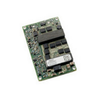
Data Sheet February 2, 2011 QPW050/060 Series DC-DC Converter Power Modules: 36-75Vdc Input; 1.2Vdc to 3.3Vdc Output; 50A/60A Output Current RoHS Compliant Applications Distributed power architectures Wireless Networks Access and Optical Network Equipment Enterprise Networks ...
Page 2
February 2, 2011 Absolute Maximum Ratings Stresses in excess of the absolute maximum ratings can cause permanent damage to the device. These are absolute stress ratings only, functional operation of the device is not implied at these or any other ...
Page 3
February 2, 2011 (continued) Electrical Specifications Parameter Output Voltage Set-point ( =25°C) IN IN,nom O O, max c Output Voltage (Over all operating input voltage, resistive load, and temperature conditions until end of life) ...
Page 4
February 2, 2011 Feature Specifications Unless otherwise indicated, specifications apply over all operating input voltage, resistive load, and temperature conditions. See Feature Descriptions for additional information. Parameter Remote On/Off Signal Interface ( open collector or IN ...
Page 5
Data Sheet February 2, 2011 Characteristic Curves The following figures provide typical characteristics for the QPW050A0F (3.3V, 50A) at 25ºC. The figures are identical for either positive or negative Remote On/Off logic ...
Page 6
Data Sheet February 2, 2011 Characteristic Curves The following figures provide typical characteristics for the QPW060A0G (2.5V, 60A) at 25ºC. The figures are identical for either positive or negative Remote On/Off logic 60A ...
Page 7
Data Sheet February 2, 2011 Characteristic Curves The following figures provide typical characteristics for the QPW060A0Y (1.8V, 60A) at 25ºC. The figures are identical for either positive or negative Remote On/Off logic 3.5 3 2.5 ...
Page 8
Data Sheet February 2, 2011 Characteristic Curves The following figures provide typical characteristics for the QPW060A0M (1.5V, 60A) at 25ºC. The figures are identical for either positive or negative Remote On/Off logic. 3 2.5 2 ...
Page 9
Data Sheet February 2, 2011 Characteristic Curves The following figures provide typical characteristics for the QPW060A0P (1.2V, 60A) at 25ºC. The figures are identical for either positive or negative Remote On/Off logic 2.5 2 1.5 ...
Page 10
... The process of determining the acceptable values of capacitance and E.S.R. is complex and is load- dependant. Lineage Power provides Web-based tools to assist the power module end-user in appraising and adjusting the effect of various load conditions and output capacitances on specific power modules for various load conditions ...
Page 11
Data Sheet February 2, 2011 (continued) Safety Considerations The input source provided with reinforced insulation from any other hazardous voltages, including the ac mains. One V pin and one V pin are ...
Page 12
Data Sheet February 2, 2011 Feature Descriptions Overcurrent Protection To provide protection in a fault output overload condition, the module is equipped with internal current-limiting circuitry and can endure current limit for few seconds. If overcurrent persists for few seconds, ...
Page 13
Data Sheet February 2, 2011 (continued) Feature Description Output Voltage Set-Point Adjustment (Trim) For output voltages: 1.5V – 3.3V 510 adj down % For ...
Page 14
Data Sheet February 2, 2011 (continued) Feature Description Output Voltage Set-Point Adjustment (Trim) Δ% = 9.1 % 100 28 V Δ 1036 ...
Page 15
Data Sheet February 2, 2011 Thermal Considerations without Baseplate The power modules operate in a variety of thermal environments; however, sufficient cooling should be provided to help ensure reliable operation. Considerations include ambient temperature, airflow, module power dissipation, and the ...
Page 16
Data Sheet February 2, 2011 The following figures provide thermal derating characteristics NATURAL CONVECTION 15 1.0 m/s (200 ft./min.) 10 2.0 m/s (400 ft./min ...
Page 17
Data Sheet February 2, 2011 The following figures provide thermal derating characteristics NATURAL CONVECTION 20 1.0 m/s (200 ft./min.) 10 2.0 m/s (400 ft./min ...
Page 18
Data Sheet February 2, 2011 Thermal Considerations with Baseplate The baseplate option (-H) power modules are constructed with baseplate on topside of the open frame power module. The baseplate includes quarter brick through-threaded 0.5 mounting hole pattern, which ...
Page 19
Data Sheet February 2, 2011 The following figures provide thermal derating characteristics Open frame 25 Baseplate 20 15 Baseplate w/ 0.25" heat sink 10 Baseplate w/ 0.5" heat sink ...
Page 20
... Pb-free solder pot is 270C max. Not all RoHS-compliant through-hole products can be processed with paste-through-hole Pb or Pb-free reflow process. If additional information is needed, please consult with your Lineage Power representative for more details. LINEAGE POWER QPW050/060 Series Power Modules; DC-DC converters 36-75Vdc Input ...
Page 21
... Tolerances: x.x mm 0.5 mm [x.xx in. 0.02 in.] (Unless otherwise indicated) x.xx mm 0.25 mm [x.xxx in 0.010 in.] TOP VIEW SIDE VIEW BOTTOM VIEW *Top side label includes Lineage Power name, product designation, and data code. LINEAGE POWER QPW050/060 Series Power Modules; DC-DC converters 36-75Vdc Input; 1.2Vdc to 3.3Vdc Output 21 ...
Page 22
... Tolerances: x.x mm 0.5 mm [x.xx in. 0.02 in.] (Unless otherwise indicated) x.xx mm 0.25 mm [x.xxx in 0.010 in.] TOP VIEW SIDE VIEW BOTTOM VIEW *Bottom side label includes Lineage Power name, product designation, and data code. LINEAGE POWER QPW050/060 Series Power Modules; DC-DC converters 36-75Vdc Input; 1.2Vdc to 3.3Vdc Output 22 ...
Page 23
Data Sheet February 2, 2011 Recommended Pad Layout for Through Hole Module Dimensions are in millimeters and (inches). Tolerances: x.x mm 0.5 mm (x.xx in. 0.02 in.) [unless otherwise indicated] x.xx mm 0.25 mm (x.xxx in ...
Page 24
... Table 1. Device Code Product codes Input Voltage QPW050A0F1 48V (36-75Vdc) QPW050A0F1Z 48V (36-75Vdc) QPW050A0F41 48V (36-75Vdc) QPW050A0F41Z 48V (36-75Vdc) QPW050A0F641Z 48V (36-75Vdc) QPW050A0F1-HZ 48V (36-75Vdc) QPW050A0F71-H 48V (36-75Vdc) QPW050A0F71-HZ 48V (36-75Vdc) QPW050A0F41-HZ 48V (36-75Vdc) QPW050A0F641-HZ 48V (36-75Vdc) QPW060A0G1 48V (36-75Vdc) QPW060A0G1Z ...