E48SR3R320NRFA Delta Electronics, E48SR3R320NRFA Datasheet - Page 11
E48SR3R320NRFA
Manufacturer Part Number
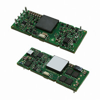
E48SR3R320NRFA
Description
MODULE DC/DC 8TH BRICK 3.3V 20A
Manufacturer
Delta Electronics
Series
DELPHIr
Type
Isolated with UVLOr
Specifications of E48SR3R320NRFA
Output
3.3V
Number Of Outputs
1
Power (watts)
66W
Mounting Type
Through Hole
Voltage - Input
36 ~ 75V
Package / Case
8-DIP Module, 1/8 Brick
1st Output
3.3 VDC @ 20A
Size / Dimension
2.30" L x 0.90" W x 0.33" H (58.4mm x 22.9mm x 8.4mm)
Power (watts) - Rated
66W
Operating Temperature
-40°C ~ 115°C
Efficiency
90.5%
Approvals
CE, cUL, TUV, UL
Lead Free Status / RoHS Status
Lead free / RoHS Compliant
3rd Output
-
2nd Output
-
4th Output
-
Other names
941-1020


DS_E48SR3R320_05142009
THERMAL CONSIDERATIONS
Thermal management is an important part of the system
design. To ensure proper, reliable operation, sufficient
cooling of the power module is needed over the entire
temperature range of the module. Convection cooling is
usually the dominant mode of heat transfer.
Hence, the choice of equipment to characterize the
thermal performance of the power module is a wind
tunnel.
Thermal Testing Setup
Delta’s DC/DC power modules are characterized in
heated vertical wind tunnels that simulate the thermal
environments
equipment. This type of equipment commonly uses
vertically mounted circuit cards in cabinet racks in which
the power modules are mounted.
The
characterization setup. The power module is mounted
on a test PWB and is vertically positioned within the
wind tunnel. The space between the neighboring PWB
and the top of the power module is constantly kept at
6.35mm (0.25’’).
Figure 20: Wind tunnel test setup
Note: Wind Tunnel Test Setup Figure Dimensions are in millimeters and (Inches)
MEASURED BELOW
following
TEMPERATURE
AIR VELOCITY
AND AMBIENT
THE MODULE
FACING PWB
encountered
figure
AIR FLOW
shows
in
PWB
50.8 (2.0”)
MODULE
12.7 (0.5”)
the
most
wind
electronics
tunnel
Thermal Derating
Heat can be removed by increasing airflow over the
module. To enhance system reliability, the power module
should always be operated below the maximum operating
temperature. If the temperature exceeds the maximum
module temperature, reliability of the unit may be affected.
THERMAL CURVES
Figure 21: Hot spot temperature measured point
*
Figure 22: Output current vs. ambient temperature and air
velocity@ V
22
20
18
16
14
12
10
8
6
4
2
0
Output Current (A)
The allowed maximum hot spot temperature is defined at 115
30
Convection
Natural
E48SR3R320(Standard) Output Current vs. Ambient Temperature and Air Velocity
35
in
=48V (Transverse Orientation)
40
100LFM
45
200LFM
@ Vin =48V (Transverse Orientation)
50
300LFM
55
400LFM
60
500LFM
65
70
Ambient Temperature (℃)
75
80
11
℃
85
Related parts for E48SR3R320NRFA
Image
Part Number
Description
Manufacturer
Datasheet
Request
R

Part Number:
Description:
Delta Electronics, Inc. [ETHERNET 10BASE-T LAN FILTER MODULES]
Manufacturer:
Delta Electronics, Inc.
Datasheet:
Part Number:
Description:
Manufacturer:
Delta Electronics, Inc.
Datasheet:
Part Number:
Description:
Manufacturer:
Delta Electronics, Inc.
Datasheet:
Part Number:
Description:
Manufacturer:
Delta Electronics, Inc.
Datasheet: