UEI25-120-D48N-C Murata Power Solutions Inc, UEI25-120-D48N-C Datasheet - Page 19
UEI25-120-D48N-C
Manufacturer Part Number
UEI25-120-D48N-C
Description
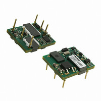
CONV DC/DC 25W 12V
Manufacturer
Murata Power Solutions Inc
Series
UEI25-120r
Type
Isolatedr
Datasheet
1.UEI25-033-D48P-C.pdf
(23 pages)
Specifications of UEI25-120-D48N-C
Number Of Outputs
1
Output
12V
Power (watts)
25W
Mounting Type
Through Hole
Voltage - Input
36 ~ 75V
Package / Case
6-DIP Module
1st Output
12 VDC @ 2.1A
Size / Dimension
1.10" L x 0.96" W x 0.32" H (27.9mm x 24.4mm x 8.1mm)
Power (watts) - Rated
25W
Operating Temperature
-40°C ~ 85°C
Efficiency
87.5%
Approvals
CAN, CSA, EN, IEC, UL
Output Power
25.2 W
Input Voltage Range
36 V to 75 V
Input Voltage (nominal)
48 V
Output Voltage (channel 1)
12 V
Output Current (channel 1)
2.1 A
Package / Case Size
24.38 mm x 27.94 mm x 8.13 mm
Output Type
DC/DC Converter
Output Voltage
12 V
Lead Free Status / RoHS Status
Lead free / RoHS Compliant
3rd Output
-
2nd Output
-
4th Output
-
Lead Free Status / Rohs Status
Lead free / RoHS Compliant
Other names
811-2222


Input Fusing
Certain applications and/or safety agencies may require fuses at the inputs of
power conversion components. Fuses should also be used when there is the
possibility of sustained input voltage reversal which is not current-limited. For
greatest safety, we recommend a fast blow fuse installed in the ungrounded
input supply line.
safety agency approvals, install the converter in compliance with the end-user
safety standard.
Input Reverse-Polarity Protection
If the input voltage polarity is reversed, an internal diode will become forward
biased and likely draw excessive current from the power source. If this source
is not current-limited or the circuit appropriately fused, it could cause perma-
nent damage to the converter.
Input Under-Voltage Shutdown and Start-Up Threshold
Under normal start-up conditions, converters will not begin to regulate properly
until the rising input voltage exceeds and remains at the Start-Up Threshold
Voltage (see Specifi cations). Once operating, converters will not turn off until
the input voltage drops below the Under-Voltage Shutdown Limit. Subsequent
restart will not occur until the input voltage rises again above the Start-Up
Threshold. This built-in hysteresis prevents any unstable on/off operation at a
single input voltage.
Shutdown whose voltage decays as input current is consumed (such as capacitor
inputs), the converter shuts off and then restarts as the external capacitor re-
charges. Such situations could oscillate. To prevent this, make sure the operating
input voltage is well above the UV Shutdown voltage AT ALL TIMES.
Start-Up Delay
Assuming that the output current is set at the rated maximum, the Vin to Vout Start-
Up Delay (see Specifi cations) is the time interval between the point when the rising
input voltage crosses the Start-Up Threshold and the fully loaded regulated output
voltage enters and remains within its specifi ed regulation band. Actual measured
times will vary with input source impedance, external input capacitance, input volt-
age slew rate and fi nal value of the input voltage as it appears at the converter.
PWM controller at power up, thereby limiting the input inrush current.
sumes that the converter already has its input voltage stabilized above the
Start-Up Threshold before the On command. The interval is measured from the
On command until the output enters and remains within its specifi ed regulation
band. The specifi cation assumes that the output is fully loaded at maximum
rated current.
Input Source Impedance
These converters will operate to specifi cations without external components,
assuming that the source voltage has very low impedance and reasonable in-
put voltage regulation. Since real-world voltage sources have fi nite impedance,
performance is improved by adding external fi lter components. Sometimes only
a small ceramic capacitor is suffi cient. Since it is diffi cult to totally characterize
The installer must observe all relevant safety standards and regulations. For
Users should be aware however of input sources near the Under-Voltage
These converters include a soft start circuit to moderate the duty cycle of the
The On/Off Remote Control interval from inception to V
TECHNICAL NOTES
OUT
regulated as-
www.murata-ps.com
all applications, some experimentation may be needed. Note that external input
capacitors must accept high speed switching currents.
converters must be driven from a source with both low AC impedance and
adequate DC input regulation. Performance will degrade with increasing input
inductance. Excessive input inductance may inhibit operation. The DC input
regulation specifi es that the input voltage, once operating, must never degrade
below the Shut-Down Threshold under all load conditions. Be sure to use
adequate trace sizes and mount components close to the converter.
I/O Filtering, Input Ripple Current and Output Noise
All models in this converter series are tested and specifi ed for input refl ected
ripple current and output noise using designated external input/output compo-
nents, circuits and layout as shown in the fi gures below. External input capaci-
tors (C
line voltage variations caused by transient IR drops in the input conductors.
Users should select input capacitors for bulk capacitance (at appropriate
frequencies), low ESR and high RMS ripple current ratings. In the fi gure below,
the C
system confi guration may require additional considerations. Please note that the
values of C
and random deviations or PARD) may be reduced by adding fi lter elements
such as multiple external capacitors. Be sure to calculate component tempera-
ture rise from refl ected AC current dissipated inside capacitor ESR. In fi gure 3,
the two copper strips simulate real-world printed circuit impedances between
the power supply and its load. In order to minimize circuit errors and standard-
ize tests between units, scope measurements should be made using BNC
connectors or the probe ground should not exceed one half inch and soldered
directly to the fi xture.
Floating Outputs
Since these are isolated DC/DC converters, their outputs are “fl oating” with
respect to their input. The essential feature of such isolation is ideal ZERO
CURRENT FLOW between input and output. Real-world converters however do
exhibit tiny leakage currents between input and output (see Specifi cations).
These leakages consist of both an AC stray capacitance coupling component
and a DC leakage resistance. When using the isolation feature, do not allow
the isolation voltage to exceed specifi cations. Otherwise the converter may
be damaged. Designers will normally use the negative output (-Output) as
Because of the switching nature of DC/DC converters, the input of these
In critical applications, output ripple and noise (also referred to as periodic
BUS
V
IN
IN
OSCILLOSCOPE
in the fi gure) serve primarily as energy storage elements, minimizing
and L
C
C
L
IN
+
+
BUS
–
–
IN
BUS
TO
, L
= 33μF, ESR < 700mΩ @ 100kHz
= 12μH
BUS
= 220μF, ESR < 100mΩ @ 100kHz
BUS
Single Output Isolated 25-Watt DC/DC Converters
components simulate a typical DC voltage bus. Your specifi c
and C
C
Figure 2. Measuring Input Ripple Current
BUS
BUS
L
may vary according to the specifi c converter model.
BUS
07 Apr 2011
CURRENT
PROBE
C
IN
UEI25 Series
MDC_UEI25W.A03 Page 19 of 23
email: sales@murata-ps.com
1
2
+INPUT
−INPUT
Related parts for UEI25-120-D48N-C
Image
Part Number
Description
Manufacturer
Datasheet
Request
R

Part Number:
Description:
CONV DC/DC 12V 25W
Manufacturer:
Murata Power Solutions Inc
Datasheet:

Part Number:
Description:
DC/DC Converters & Regulators 48V 12Vout 2.1A SMT 25.2W Neg. Polarity
Manufacturer:
Murata Power Solutions Inc
Datasheet:
Part Number:
Description:
DC/DC Converters & Regulators 48V 12Vout 2.1A SMT 25.2W Pos. Polarity
Manufacturer:
Murata Power Solutions Inc
Datasheet:
Part Number:
Description:
CONV DC/DC 5V 25W
Manufacturer:
Murata Power Solutions Inc
Datasheet:
Part Number:
Description:
CONV DC/DC 3.3V 25W
Manufacturer:
Murata Power Solutions Inc
Datasheet:

Part Number:
Description:
CONV DC/DC 25W 3.3V
Manufacturer:
Murata Power Solutions Inc
Datasheet:
Part Number:
Description:
CONV DC/DC 25W 5V
Manufacturer:
Murata Power Solutions Inc
Datasheet:
Part Number:
Description:
DC/DC Converters & Regulators 48V 3.3Vout 7.5A SMT 25W Pos. Polarity
Manufacturer:
Murata Power Solutions Inc
Datasheet:
Part Number:
Description:
DC/DC Converters & Regulators 48Vin 5Vout 5A SMT 25W Pos. Polarity
Manufacturer:
Murata Power Solutions Inc
Datasheet:
Part Number:
Description:
DC/DC Converters & Regulators 48V 3.3Vout 7.5A SMT 25W Neg. Polarity
Manufacturer:
Murata Power Solutions Inc
Datasheet:

Part Number:
Description:
DC/DC TH Q12-15V UEI
Manufacturer:
Murata Power Solutions Inc
Datasheet:

Part Number:
Description:
Transformers 5Vin 5Vout 200mA 4000Vdc 1:1.33 turn
Manufacturer:
Murata Power Solutions Inc
Datasheet:

Part Number:
Description:
POWER SUPPLY
Manufacturer:
Murata Power Solutions Inc
Datasheet:

Part Number:
Description:
DPM LED MINI 2VDC 3.5DIG LP RED
Manufacturer:
Murata Power Solutions Inc
Datasheet:

Part Number:
Description:
CONV DC/DC 1W 5VIN 5VOUT SIP SGL
Manufacturer:
Murata Power Solutions Inc
Datasheet: