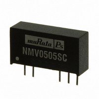
FEATURES
PRODUCT OVERVIEW
The NMV series of industrial temperature range
DC/DC converters are the standard buliding blocks
for on-board distributed power systems. They
are ideally suited for providing local supplies on
control system boards with the added benefi t
of 3kVDC galvanic isolation to reduce switch-
ing noise. Available in SIP and DIP with dual and
single output pinout. All of the rated power may
be drawn from a single pin provided the total load
does not exceed 1 watt.
www.murata-ps.com
www.murata-ps.com
RoHS compliant
Effi ciency to 79%
Power density up to 0.85W/cm
Wide temperature performance at full
1 Watt load, –40°C to 85°C
Single or dual output
UL 94V-0 package material
No heatsink required
Footprint from 1.17cm
Industry standard pinout
Power sharing on dual output
3kVDC isolation (1 minute)
5V, 12V, & 15V input
5V, 9V, 12V and 15V output
Internal SMD construction
Fully encapsulated with toroidal
magnetics
No external components required
MTTF up to 4.2 million hours
No electrolytic or tantalum capacitors
www.murata-ps.com/rohs
For full details go to
2
3
1. Calculated using MIL-HDBK-217F with nominal input voltage at full load.
All specifi cations typical at T
SELECTION GUIDE
NMV0505DAC
NMV0509DAC
NMV0512DAC
NMV0515DAC
NMV0505SAC
NMV0509SAC
NMV0512SAC
NMV0515SAC
NMV1205DAC
NMV1209DAC
NMV1212DAC
NMV1215DAC
NMV1205SAC
NMV1209SAC
NMV1212SAC
NMV1215SAC
NMV1505SAC
NMV1512SAC
NMV1515SAC
NMV0505DC
NMV0509DC
NMV0512DC
NMV0515DC
NMV0505SC
NMV0509SC
NMV0512SC
NMV0515SC
NMV1205DC
NMV1209DC
NMV1212DC
NMV1215DC
NMV1205SC
NMV1209SC
NMV1212SC
NMV1215SC
NMV1505SC
NMV1512SC
NMV1515SC
INPUT CHARACTERISTICS
Parameter
Voltage range
Refl ected ripple current
Order Code
12
12
12
12
12
12
12
12
15
15
15
12
12
12
12
12
12
12
12
15
15
15
V
5
5
5
5
5
5
5
5
5
5
5
5
5
5
5
5
A
=25°C, nominal input voltage and rated output current unless otherwise specifi ed.
±12
±15
±12
±15
±12
±15
±12
±15
±12
±15
±5
±9
±5
±9
±5
±9
±5
±9
±5
12
15
12
15
12
15
12
15
12
15
Conditions
Continuous operation, 5V input types
Continuous operation, 12V input types
Continuous operation, 15V input types
V
5
9
5
9
5
9
5
9
5
±100
±100
±100
±100
±100
±55
±42
±33
±55
±42
±33
±55
±42
±33
±55
±42
±33
±42
±33
200
111
200
111
200
111
200
111
200
mA
3kVDC Isolated 1W Single & Dual Output DC/DC Converters
84
67
84
67
84
67
84
67
84
67
Technical enquiries email: mk@murata-ps.com, tel: +44 (0)1908 615232
NMV 5V, 12V & 15V Series
294
267
260
256
294
267
260
256
121
113
108
108
121
113
108
108
280
263
256
253
280
263
256
253
117
113
111
110
117
113
111
110
mA
93
85
84
91
87
84
14.6
14.6
14.6
14.6
9.3
7.4
6.7
9.3
7.4
6.7
9.3
7.4
6.7
9.3
7.4
6.7
8.3
3.3
2.8
9.0
7.5
6.8
6.8
9.0
7.5
6.8
6.8
9.0
7.5
6.8
6.8
9.0
7.5
6.8
6.8
5.5
2.6
2.3
%
8.0
7.3
8.0
7.3
8.0
7.3
8.0
7.3
4.0
4.0
8.5
7.5
8.5
8.5
7.5
8.5
8.5
7.5
8.5
8.5
7.5
8.5
3.0
3.0
15
10
15
10
15
10
15
10
10
10
10
10
10
10
11.3
10.5
15.5
11.2
8.7
9.5
7.5
8.5
7.5
6.7
6.7
6.3
8.6
6.5
6.2
5.5
6.5
7.5
7.5
15
16
12
11
11
11
11
11
11
10
11
7
8
8
9
6
7
8
6
mVp-p
2010-09-20 KDC_NMV.G01 Page 1 of 5
Min.
10.8
13.5
8.5
9.4
8.2
8.5
4.5
17
15
16
11
23
15
15
14
14
19
17
16
14
22
17
17
14
13
14
17
12
13
11
10
13
12
9
9
9
8
9
8
9
9
71.5
71.5
68
75
77
78
68
75
77
78
69
74
77
77
69
74
77
77
67
75
77
76
78
79
76
78
79
71
74
75
76
71
74
75
76
69
75
77
%
Typ.
12
15
20
5
pF
23
30
26
27
23
30
26
27
26
35
43
42
26
35
43
42
21
45
50
21
24
26
27
21
24
26
27
27
35
42
41
27
35
42
41
39
68
84
Max.
13.2
16.5
5.5
40
4241
3376
2555
1838
4241
3376
2555
1838
2664
2295
1883
1462
2664
2295
1883
1462
2747
1365
3106
2258
1579
1065
3106
2258
1579
1065
2148
1705
1287
2148
1705
1287
1941
kHrs
941
924
924
789
522
mA p-p
Units
V
DIP
SIP
DIP
SIP
DIP
SIP
DIP
SIP


