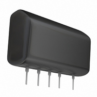
BP5041A5 Rohm Semiconductor, BP5041A5 Datasheet

BP5041A5
Specifications of BP5041A5
Related parts for BP5041A5
BP5041A5 Summary of contents
Page 1
... converter BP5041A / BP5041A5 / BP5041A15 The BP5041A, BP5041A5 and BP5041A15 are AC/DC converters which can be used to supply DC output from a commercial power supply (200 to 230V AC). Using these modules enable simple, easy drive of microcomputers, LEDs, and other electronic components without using a transformer. They also allow set PCBs to be kept compact and lightweight, with extremely few attachments ...
Page 2
... Line regulation Vl Load regulation Vp Output ripple voltage η Conversion efficiency ∗1 Maximum output current varies depending on ambient temperature; please refer to derationg curve. ∗ 2 Spike noise is not included in output ripple voltage. BP5041A / BP5041A5 / BP5041A15 Min. Typ. Max. Unit 226 282 390 V (DC) Min ...
Page 3
... Use a low-impedance product for switching power supplies for the output capacitor Application example Half wave rectifier circuit 0.1µ 4.7µF / 450V BP5041A / BP5041A5 / BP5041A15 BP5041A / BP5041A5 / BP5041A15 100µ / 50V Fig.1 Full wave rectifier circuit BP5041A / BP5041A5 / BP5041A15 5 ...
Page 4
... The ESR of the capacitor affects the output ripple voltage. (4) CR filter should be placed between R1 and C3 in order to lower the fine-noise voltage; R1 should be 1/4W and 10Ω ∼ 22 Ω should be a film capacitor and 400V or higher. Make sure to place C3 as near as possible to the modules. BP5041A / BP5041A5 / BP5041A15 BP5041A 5 1 ...
Page 5
... The measurement circuit diagram below (Fig.6) was used in the test whose results are shown in Fig.5. 100 MKR 504.4 kHz 90 48.05 dBµ 100k 1M 10M FREQUENCY (Hz) Fig.5 Pin noise voltage 50µH 1µF AC-200V 50µH BP5041A / BP5041A5 / BP5041A15 100M 10 0.22µF 4.7µF 0.1µF V 1kΩ 0.1µF Fig.6 BP5041A / BP5041A5 / BP5041A15 100µF ...
Page 6
... AMBIENT TEMPERATURE : Ta (°C) Fig.7 Derating curve 100 100 OUTPUT CURRENT : I (mA) O Fig.10 Conversion efficiency BP5041A / BP5041A5 / BP5041A15 100 OUTPUT CURRENT : I (mA) O Fig.8 Surface temperature rise 5.5 5.4 5.3 5.2 5.1 5 4.9 4.8 4.7 4.6 4 100 OUTPUT CURRENT : I (mA) O Fig.9 Output characteristic ...
Page 7
... Fig.11 Derating curve 100 100 120 OUTPUT CURRENT : I (mA) O Fig.14 Conversion efficiency BA5041A15 − AMBIENT TEMPERATURE : Ta (°C) Fig.15 Derating curve BP5041A / BP5041A5 / BP5041A15 100 120 OUTPUT CURRENT : I (mA) O Fig.12 Surface temperature rise 100 OUTPUT CURRENT : I (mA) O Fig.16 Surface temperature rise 13 12.8 12.6 12 ...
Page 8
... Power Module 100 100 OUTPUT CURRENT : I (mA) O Fig.18 Conversion efficiency ! ! ! ! External dimensions (Units : mm) 32.5Max 0.5±0.1 3.25Max. 1.3±0 5.08±0.2 22.86 (Typ.) SIP10 BP5041A / BP5041A5 / BP5041A15 11.5Max. 0.25±0.05 6.75Max. 4.75Max. ...
Page 9
Appendix No technical content pages of this document may be reproduced in any form or transmitted by any means without prior permission of ROHM CO.,LTD. The contents described herein are subject to change without notice. The specifications for the product ...


