Electrical Characteristics
Standard Resistance Range
Resistance Tolerance ........... ±20 % std.
End Resistance ..... 1 % or 2 ohms max.
Contact Resistance Variation
Resolution ................................... Infi nite
Insulation Resistance ............... 500 vdc.
Dielectric Strength
Adjustment Angle ................. 210 ° nom.
Environmental Characteristics
Power Rating (300 volts max.)
Temperature Range ... -55 °C to +125 °C
Temperature Coeffi cient ... ±100 ppm/°C
Humidity ............................90-98 % RH,
Vibration .....20 G TRS ±1 %; VRS ±1 %
Shock .......100 G TRS ±1 %; VRS ±1 %
Load Life
Rotational Life .......................100 cycles
Thermal Shock .........................5 cycles
Physical Characteristics
Mechanical Angle ................. 240 ° nom.
Torque ..........................180 g-cm typical
Stop Strength ..............300 g-cm typical
Pushover Strength (Z Style)
Weight ............... Approximately 0.01 oz.
Marking .................Manufacturer’s code,
Wiper ............... 50 % (Actual TR) ±10 %
Flammability ..........................U.L. 94V-0
Standard Packaging
Adjustment Tool ..............................H-90
TOLERANCES: ±
*RoHS Directive 2002/95/EC Jan 27 2003 including Annex.
Specifi cations are subject to change without notice.
Customers should verify actual device performance in their specifi c applications.
Sea Level............... 500 vac (1 minute)
70 °C .................................... 0.25 watt
125 °C ....................................... 0 watt
J, G and R ................ 500 pcs./7 ” reel
S and Z ..................... 200 pcs./7 ” reel
H ....................................100 pcs./tube
.....................10 ohms to 2 megohms
.................................... 3 % or 3 ohms
....(@ 70 °C Rated Power 1000 Hours)
...........2 kilograms (4.4 lbs.) minimum
DIMENSIONS:
resistance code and date code
(see standard resistance table)
TRS ±2 %; IR 10 megohms
(tighter tolerance available)
(.010)
0.25
TRS ±2 %; VRS ±1 %
(whichever is greater)
10 cycles, 240 hours
100 megohms min.
(INCHES)
EXCEPT WHERE NOTED
MM
TRS ±3 %
TRS ±3 %
3314G-1
Features
■
■
■
■
(.197)
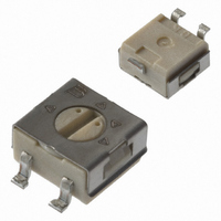
3314 - 4 mm Square Trimpot
3314J-1
5.00
(.244)
6.20
Product Dimensions
Surface Mount / Single Turn / Cermet
Industrial / Sealed
Compatible with surface mount
manufacturing processes
Compatible with popular vacuum
pick-and-place equipment
J-hook, gull-wing and pinned
confi gurations
(.093)
3
2.35
(.177)
4.50
2
(.197)
5.00
3
1
(.177)
(.197)
4.50
5.00
2
1
(.177)
4.50
(.093)
(.031 ± .004)
2.35
(.051 ± .004)
(.031 ± .004)
0.8 ± 0.1
2 PLCS.
1.30 ± 0.1
3 PLCS.
(.177)
0.8 ± 0.1
(.051 ± .004)
(.040)
4.50
2 PLCS.
1.30 ± 0.1
1.0
3 PLCS.
(.051)
1.3
(.100)
2.55
(.100)
2.55
RECOMMENDED PCB
LAYOUT
RECOMMENDED PCB
LAYOUT
5° MAX.
3 PLCS.
(.079)
TYP.
2.0
(.079)
(.079)
(.091)
(.091)
(.024)
2.0
2.0
2.3
2.3
0.6
2 PLCS.
2 PLCS.
(.157)
(.008)
(.051)
(.217)
(.051)
(.008)
4.00
0.20
TYP.
1.3
0.20
5.5
TYP.
1.3
TYP.
®
■
■
■
■
3314J-1, G-1, R-1, H-1
(Bourns Marking,
Straight Slot)
3314J-3, G-3, R-3, H-3
(Reverse Marking,
Straight Slot)
Trimming Potentiometer
Model
Style
Standard or Modifi ed Product
Indicator (Styles J, G, R, H & S)
Product Indicator (Style Z only)
Resistance Code
Embossed Tape Designator**
**Style H is available in tube packaging only.
Popular distribution values listed in boldface.
Special resistances available.
3
3
How To Order
Side adjust available
Meets EIA/EIAJ/IPC/VECI SMD standard
trimmer designs
RoHS compliant* - see
information
trimmers
For trimmer applications/processing
guidelines,
-1 = Single Slot
-2 = Cross Slot
-3 = Single Slot w/Reverse Marking
-4 = Cross Slot w/Reverse Marking
-GA4 = Single Slot
-1 = Cross Slot
-3 = Single Slot w/Reverse Marking
-4 = Cross Slot w/Reverse Marking
E = Styles J, G and R: 500 pcs./7 ” reel
G = Styles J and G: 3000 pcs./13 ” reel
Standard Resistance Table
2
2
COMMON DIMENSIONS -
COMMON DIMENSIONS -
1
1
Resistance
Styles S and Z: 200 pcs./7 ” reel
Style R: 2500 pcs./13 ” reel
Styles S and Z: 1000 pcs./13 ” reel
1,000,000
2,000,000
100,000
200,000
250,000
500,000
ALL PIN STYLES:
ALL PIN STYLES:
(Ohms)
10,000
20,000
50,000
X
X
X
X
1,000
2,000
5,000
100
200
500
STRAIGHT
ADJ. SLOT
(.096)
(.020)
(.020)
STRAIGHT
ADJ. SLOT
(.096)
(.020)
(.020)
10
20
50
2.45
2.45
.51
.51
.51
.51
click here
on lead free surface mount
LONG
WIDE
LONG
WIDE
DEEP
DEEP
3314J-2, G-2, R-2, H-2
(Bourns Marking,
Cross Slot)
3314J-4, G-4, R-4, H-4
(Reverse Marking,
Cross Slot)
3314 J - 1 - 502 E
3
3
processing
2
2
Resistance
COMMON DIMENSIONS -
COMMON DIMENSIONS -
1
1
ALL PIN STYLES:
ALL PIN STYLES:
Code
X
X
X
X
100
200
500
101
201
501
102
202
502
103
203
503
104
204
254
504
105
205
ADJ. SLOT
(.095)
(.020)
(.020)
ADJ. SLOT
(.095)
(.020)
(.020)
CROSS
CROSS
2.41
2.41
.51
.51
.51
.51
LONG
WIDE
LONG
WIDE
DEEP
DEEP