51AAA-B24-B20 Bourns Inc., 51AAA-B24-B20 Datasheet - Page 3
51AAA-B24-B20
Manufacturer Part Number
51AAA-B24-B20
Description
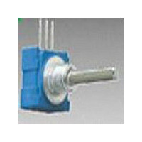
PANEL CONTROL POT
Manufacturer
Bourns Inc.
Series
50r
Type
Potentiometerr
Datasheet
1.51CAD-E24-A15L.pdf
(3 pages)
Specifications of 51AAA-B24-B20
Number Of Turns
Single
Termination Style
Through Hole
Temperature Coefficient
±1000ppm/°C
Resistance (ohms)
100K
Power (watts)
0.5W, 1/2W
Tolerance
±20%
Rotation
290°
Adjustment Type
Side Adjustment
Resistive Material
Conductive Plastic
Actuator Length
19.05mm
Actuator Type
Slotted Shaft
Actuator Diameter
6.35mm
Package / Case
Square - 0.521" L x 0.492" W x 0.350" H (13.23mm x 12.50mm x 8.89mm)
Resistance In Ohms
100K
Resistance
100kohm
Power Rating
1/2W
Tolerance (+ Or -)
20%
Mounting Style
Panel
Operating Temp Range
1C to 125C
Failure Rate
Not Required
Shaft Diameter (mm)
6.35mm
Product Diameter (mm)
Not Requiredmm
Product Length (mm)
27.94mm
Product Height (mm)
13.25mm
Product Depth (mm)
12.5mm
Taper
Linear
Element Type
Conductive Plastic
Shaft Type
Slotted
Shaft Length
3/4 in
Shaft Diameter
1/4 in
Operating Temperature Range
+ 1 C to + 125 C
Product
Panel Mount Potentiometers
Lead Free Status / Rohs Status
Lead free / RoHS Compliant
Other names
Q2531354


(.250)
(.236)
(.250)
6.35
6.35
(.125)
(.118)
(.157)
6.0
3.18
(3.18)
.125
3.0
4.0
Shaft/Bushing Styles
SHAFT
SHAFT
SHAFT
SHAFT
SHAFT
SHAFT
SHAFT
(.375)
(.374)
51/53 - Sealed 1/2 ” (12.5 mm) Square Control
9.53
9.5
12.70
3/8-32UNEF-2A
1/4-32UNEF-2A
3/8-32UNEF-2A
(.500)
1/4-32UNEF-2A
M10 X 0.75-6g
M6 X .075-6g
M7 X .075-6g
(.394)
(.375)
10.0
(.375)
9.53
(2.36)
(2.75)
(.250)
9.53
6.35
6.0
7.0
(6.35)
(.315)
.250
(.250)
.315
(8.0)
6.35
8.0
(.375)
9.53
BUSHING
BUSHING
BUSHING
BUSHING
BUSHING
BUSHING
BUSHING
(.060 ± .010)
1.52 ± 0.25
MAX. FLAT LENGTH
(.031 ± .010)
(.063 ± .010)
(.031 ± .010)
(.071 ± .010)
0.79 ± 0.25
(.060 ± .010)
(.060 ± .010)
1.60 ± 0.25
0.79 ± 0.25
1.80 ± 0.25
1.52 ± 0.25
1.52 ± 0.25
(.031 ± .004)
OPT.
(0.79 ± 0.10)
(.031 ± .004)
(.039 ± .004)
0.79 ± 0.10
(.031 ± .004)
1.194 ± 0.10
(.047 ± .004)
(.216 ± .005)
.031 ± .004
0.79 ± 0.10
1.00 ± 0.10
0.79 ± 0.10
5.49 ± 0.10
15.88
(.625)
OPT.
OPT.
OPT.
DIMENSIONS:
OPT.
OPT.
OPT.
OPT.
A Style Bushing -
C Style Bushing
U Style Bushing
R Style Bushing
A Style Bushing
F Style Bushing
S Style Bushing
1.000
1.000
1.000
1.000
STD. LENGTH ‘L’
STD. LENGTH ‘L’
Flatted Shaft
STD. LENGTH ‘L’
STD. LENGTH ‘L’
STD. LENGTH ‘L’
STD. LENGTH ‘L’
STD. LENGTH ‘L’
.500
.625
.750
.875
.375
.500
.625
.750
.875
.625
.750
.875
.625
.750
.875
.394
.512
.630
.866
.984
.394
.512
.630
.866
.984
.512
.630
.866
.984
(INCHES)
(15.88)
(19.05)
(22.23)
(15.88)
(19.05)
(22.23)
(15.88)
(19.05)
(22.23)
(15.88)
(19.05)
(22.23)
MM
(12.7)
(25.4)
(9.53)
(12.7)
(25.4)
(25.4)
(25.4)
(10.0)
(13.0)
(16.0)
(22.0)
(25.0)
(10.0)
(13.0)
(16.0)
(22.0)
(25.0)
(13.0)
(16.0)
(22.0)
(25.0)
Boldface features are Bourns standard options. All others are available with higher
minimum order quantities.
Code
Code
51
53
A
B
C
D
E
R
U
T
How To Order
51
Code
BUSHING CONFIGURATION
A
C
R
U
F
S
Code
M
A
B
C
D
E
G
H
K
F
J
L
Description
PC Pins (.100 ” centers)
Solder Lugs
# SECTIONS/DETENTS
SHAFT TYPE
Description
Single Plain 1/4 ”D
Single Slotted 1/4 ”D
Single Flatted 1/4 ”D
Single Plain 1/8 ”D
Single Slotted 1/8 ”D
Single Slotted 6 mmD
Single Slotted 4 mmD
Single Slotted 3 mmD
Code
Description
3/8 ” D x 3/8 ” L
1/4 ” D x 1/4 ” L
1/4 ” D x 1/2 ” L
10 mm D x 9.5 mm L
6 mm D x 8 mm L
7 mm D x 8 mm L
M
MODEL
A
C
D
L
N
MOUNTING BRACKET/
Description
Single No Detent
Double No Detent
Triple No Detent
Quad No Detent
Single w/Center Detent
Double w/Center Detent
Triple w/Center Detent
Quad w/Center Detent
Five Section
Six Section
Five Section w/Detent
Six Section w/Detent
ANTI-ROTATION LUG
A
Description
AR Lug 90 °CW
AR Lug 270 °CW
No AR Lug or Bracket
Front Bracket
Rear Bracket
Front and Rear Bracket
A
BUSHINGS
Customers should verify actual device performance in their specifi c applications.
D
Code
AVAILABLE ONLY IN
C, F
C, F
A
A
A
R
U
S
12,16,20,24,28,32
12,16,20,24,28,32
-
16,20,24,28,32
10,13,16,22,25
10,13,16,22,25
10,13,16,22,25
Description
20,24,28,32
20,24,28,32
LENGTHS
Code
(A)
(H)
(B)
(C)
(D)
(G)
(E)
(F)
(S)
(T)
(Y)
TYPE/TOLERANCE
B
ELEMENT TAPER
Description
Linear Cermet ±10 %
Linear Cermet ±5 %
Linear C-P ±20 %
Linear C-P ±10 %
CW Audio Cermet
±10 %
CCW Audio Cermet
±10 %
CW Audio C-P ±20 %
CW Audio C-P ±10 %
CCW Audio C-P
±20 %
CCW Audio C-P
±10 %
CW Dual Audio
Taper C-P ±20 %
Specifi cations are subject to change without notice.
28
Code
12
16
20
24
28
32
10
13
16
22
25
LENGTH
-
(FMS)
SHAFT
Description
3/8 ”
1/2 ”
5/8 ”
3/4 ”
7/8 ”
1 ”
10 mm
13 mm
16 mm
22 mm
25 mm
(28) — 150
(06) — 200
(07) — 250
(08) — 500
(09) — 750
(10) — 1 K
(29) — 1.5 K
(11) — 2 K
(12) — 2.5 K
(13) — 5 K
(10) — 1 K
(12) — 2.5 K
(13) — 5 K
(15) — 10 K
(16) — 20 K
(17) — 25 K
(10) — 1 K
(12) — 2.5 K
(13) — 5 K
(15) — 10 K
(17) — 25 K
(10) — 1 K
(12) — 2.5 K
(13) — 5 K
(15) — 10 K
(17) — 25 K
(10) — 1 K
(12) — 2.5 K
(13) — 5 K
(15) — 10 K
(17) — 25 K
(10) — 1 K
(12) — 2.5 K
(13) — 5 K
(15) — 10 K
(17) — 25 K
A
Metric
VALUE IN OHMS
RESISTANCE
Code
(CODE)
RoHS IDENTIFIER
L
REV. 09/22/10
AVAILABLE
BUSHING
R, S, U, T
R, S, U, T
R, S, U, T
R, S, U, T
R, S, U, T
15
ONLY IN
A, C, F
A, C, F
A, C, F
A, C, F
Description
Compliant
Code
B, C
A, C
(14) — 7.5 K
(15) — 10 K
(30) — 15 K
(16) — 20 K
(17) — 25 K
(18) — 50 K
(19) — 75 K
(20) — 100 K
(23) — 500 K
(25) — 1 M
(18) — 50 K
(20) — 100 K
(22) — 250 K
(23) — 500 K
(25) — 1 M
(18) — 50 K
(20) — 100 K
(23) — 500 K
(25) — 1 M
(18) — 50 K
(20) — 100 K
(22) — 250 K
(23) — 500 K
(25) — 1 M
(18) — 50 K
(20) — 100 K
(22) — 250 K
(23) — 500 K
(25) — 1 M
(18) — 50 K
(20) — 100 K
(22) — 250 K
(23) — 500 K
(25) — 1 M
L
Related parts for 51AAA-B24-B20
Image
Part Number
Description
Manufacturer
Datasheet
Request
R

Part Number:
Description:
POT 1K OHM 1/2" SQ 1W CERMET
Manufacturer:
Bourns Inc.
Datasheet:
Part Number:
Description:
POT 5K OHM 1/2" SQ 1W CERMET
Manufacturer:
Bourns Inc.
Datasheet:
Part Number:
Description:
POT 10K OHM 1/2" SQ 1W CERMET
Manufacturer:
Bourns Inc.
Datasheet:
Part Number:
Description:
POT 1K OHM 1/2" SQ 1/2W PLAS
Manufacturer:
Bourns Inc.
Datasheet:
Part Number:
Description:
POT 5K OHM 1/2" SQ 1/2W PLAS
Manufacturer:
Bourns Inc.
Datasheet:
Part Number:
Description:
POT 10K OHM 1/2" SQ 1/2W PLAS
Manufacturer:
Bourns Inc.
Datasheet:
Part Number:
Description:
POT 50K OHM 1/2" SQ 1/2W PLAS
Manufacturer:
Bourns Inc.
Datasheet:
Part Number:
Description:
POT 1K OHM 1/2" SQ 1/4W PLAS
Manufacturer:
Bourns Inc.
Datasheet:
Part Number:
Description:
POT 10K OHM 1/2" SQ 1/4W PLAS
Manufacturer:
Bourns Inc.
Datasheet:
Part Number:
Description:
POT 50K OHM 1/2" SQ 1/4W PLAS
Manufacturer:
Bourns Inc.
Datasheet:

Part Number:
Description:
Manufacturer:
Bourns, Inc.
Datasheet:
Part Number:
Description:
11mm Potentiometer
Manufacturer:
Bourns, Inc.
Datasheet: